


M300EU GETTING STARTED
(Addendum to M300EU Manual - P/N 04145)
3. GETTING STARTED
3.1. UNPACKING THE M300EU
Unpack the M300EU as per the directions in Section 3.1 of the M300E/EM manual (P/N 04288), with the
exception that there are no shipping screws.
3.2. M300EU ANALYZER LAYOUT
The front panel of the M300EU is identical to that of the M300E/EM (see Figure 3-1 of the M300E/EM Operators
Manual (P/N 04288). The Rear Panel is also very similar to that of the M300E/EM, the only difference being that
the instrument’s particulate filter is mounted externally on the upper left side of the rear panel rather than
internally as on the M300E/EM.
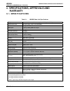
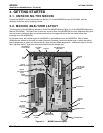
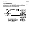
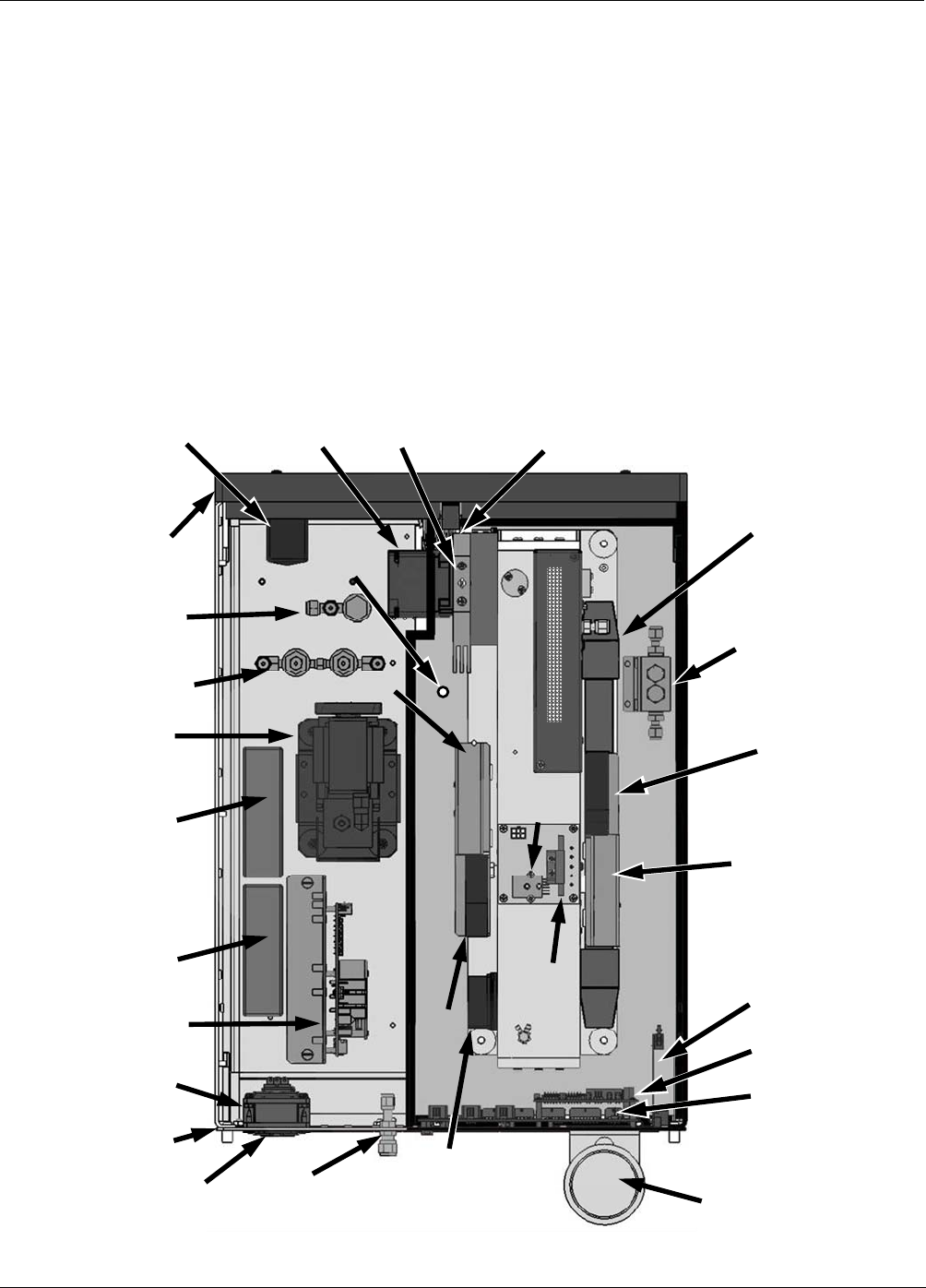
On the other hand, the internal layout of the M300EU is quite different from the M300E/EM. Most of these
differences are related to the need to create a thermally insulated, convection-heated oven in which the optical
bench temperature is raised and maintained at a high and very stable temperature. Additionally there is a multi-
tube, high flow Nafion
®
dryer that removes moisture from the sample gas.
Particulate Filter
Optional
Zero /Sample/Cal
Valves
Nafion
®
Dryer
Auto-Ref
V
alve
& CO Scrubber
Assembly
OPTICAL BENCH
SYNC/DEMOD PCA
IR Source
GFC Wheel
Motor
On/Of Switch &
Circuit Breaker
GFC Wheel Housing
& Heat Sync
Optional
Ethernet
PCA
CPU
Motherboard
Oven Heater 1
Oven Heater 2
Oven
Fan
Fan
Gas inlets &
Outlets
AC Power
Receptacle
(under fan)
Relay PCA
+12 VDC
Power Supply
Internal
Pump
Gas
Flow
Sensor
Gas
Pressure
Sensor
Front
Panel
REAR
Panel
Main
Cooling Fan
INSULATED OVEN AREA
Oven
Temperature
Sensor
Motherboard
Stabilization Fan
±5 VDC
Power Supply
Optional
Shutoff Valve
Figure 3-1: M300EU Internal Layout
05514 Rev A1 5