


TROUBLESHOOTING & REPAIR M300EU
Addendum to M300E/EM Manual P/N 04288
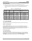
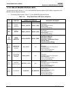
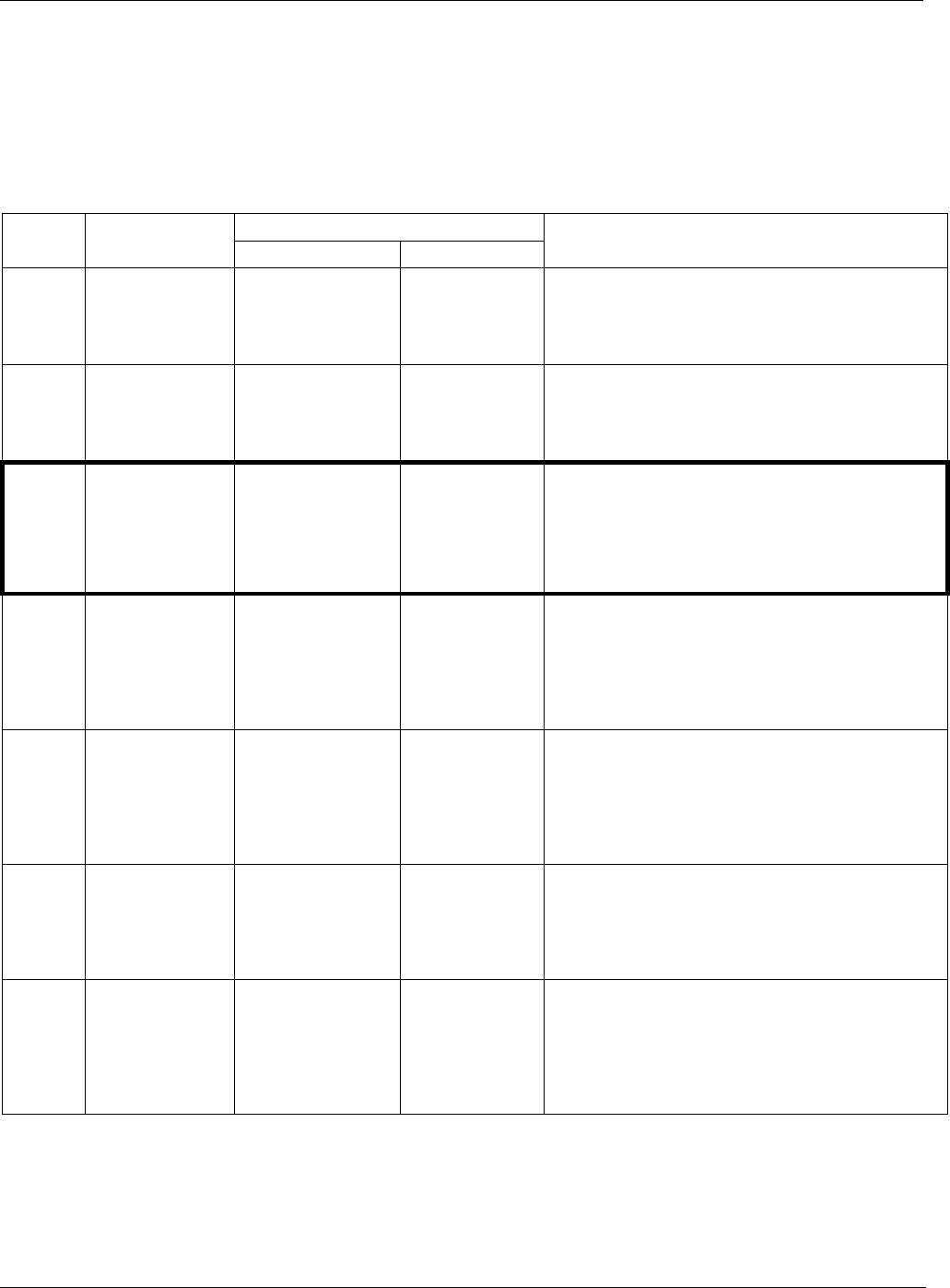
11.2.2. RELAY BOARD STATUS LED’S
The information found in Section 11.1.4.3 of the M300E/EM Operators Manual (P/N 04288) is applicable to the
M300EU with the following exception:
• The following table replaces Table 11-5 of the M300E/EM Operators Manual.
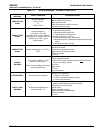
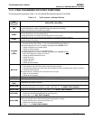
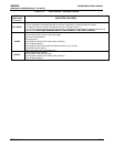
Table 11-3: Relay Board Status LED Failure Indications
SIGNAL I/O PARAMETER
LED FUNCTION
ACTIVATED BY VIEW RESULT
DIAGNOSTIC TECHNIQUE
D2
Yellow
WHEEL
HEATER
WHEEL_HEATER WHEEL_TEMP
Voltage displayed should change. If not:
Failed Heater
Faulty Temperature Sensor
Failed AC Relay
Faulty Connectors/Wiring
D3
Yellow
BENCH
HEATER
BENCH_HEATER BENCH_TEMP
Voltage displayed should change. If not:
Failed Heater
Faulty Temperature Sensor
Failed AC Relay
Faulty Connectors/Wiring
D4
Yellow
OVEN
HEATERS
OVEN_HEATER OVEN_TEMP
Voltage displayed should change. If not:
Failed Oven Heater(s)
Failed Oven Fans(s)
Faulty Oven Temperature Sensor
Failed AC Relay
Faulty Connectors/Wiring
D5
Green
SAMPLE/CAL
GAS VALVE
OPTION
CAL_VALVE
N/A
Sample/Cal Valve should audibly change states. If
not:
Failed Valve
Failed Relay Drive IC on Relay Board
Failed Relay Board
Faulty +12 VDC Supply (PS2)
Faulty Connectors/Wiring
D6
Green
ZERO/SPAN
GAS VALVE
OPTION
SPAN_VALVE
N/A
Zero/Span Valve should audibly change states. If
not:
Failed Valve
Failed Relay Drive IC on Relay Board
Failed Relay Board
Faulty +12 VDC Supply (PS2)
Faulty Connectors/Wiring
D7
Green
SHUTOFF
VALVE OPTION
SHUTOFF_VALVE
N/A
Shutoff Valve should audibly change states. If not:
Failed Valve
Failed Relay Drive IC on Relay Board
Failed Relay Board
Faulty +12 VDC Supply (PS2)
Faulty Connectors/Wiring
D8
Green
IR SOURCE
IR_SOURCE CO_MEASURE
Voltage displayed should change. If not:
Failed IR Source
Faulty +12 VDC Supply (PS2)
Failed Relay Board
Failed IR Photo-Detector
Failed Sync/Demod Board
Faulty Connectors/Wiring
64 05514 Rev A1