


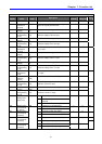

Chapter 7. Function list
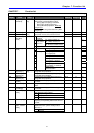
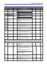
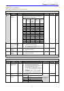
Function group 2
LED
display
Parameter
name
Min/Max
range
Description
Factory
defaults
Adjustable
during run
Page
H 0 [Jump code] 1/95 This parameter sets the code number to
jump.
1 O 5-5
H 1 [Fault history
1]
- nOn -
H 2 [Fault history
2]
- nOn -
H 3 [Fault history
3]
- nOn -
H 4 [Fault history
4]
- nOn -
H 5 [Fault history
5]
-
This parameter stores information on the
types of faults, the frequency, the current
and the Accel/Decel condition at the time of
fault.
The last fault is automatically stored in
the H 1- [Fault history 1].
nOn -
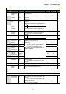
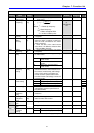
H 6 [Reset fault
history]
0/1 This parameter clears the fault history
saved in H 1-5.
0 O
11-4
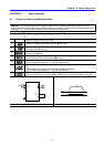
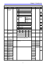
H 7 [Dwell
frequency]
F23/400
[Hz]
When run frequency is issued, motor
starts to accelerate after dwell frequency is
applied to the motor during H8- [Dwell time].
[Dwell frequency] can be set within the
range of F21- [Max frequency] and F23-
[Start frequency].
5.0 X
H 8 [Dwell time] 0/10 [sec] This parameter sets the time for dwell
operation.
0.0 X
10-5
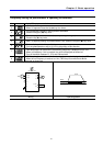
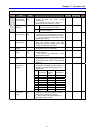
H10 [Skip
frequency
select]
0/1 This parameter sets the frequency range
to skip to prevent undesirable resonance
and vibration on the structure of the
machine.
0 X
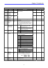
H11
1)
[Skip
frequency low
limit 1]
10.0 X
H12 [Skip
frequency high
limit 1]
15.0 X
H13 [Skip
frequency low
limit 2]
20.0 X
H14 [Skip
frequency high
limit 2]
25.0 X
H15 [Skip
frequency low
limit 3]
30.0 X
H16 [Skip
frequency high
limit 3]
0/400
[Hz]
Run frequency cannot be set within the
range of H11 thru H16.
The frequency values of the low
numbered parameters cannot be set above
those of the high numbered ones.
35.0 X
9-20
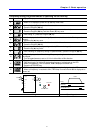
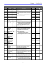
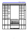
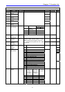
H17 S-Curve
accel/decel
start side
1/100 [%] Set the speed reference value to form a curve
at the start during accel/decel. If it is set
higher, linear zone gets smaller.
40 X
H18 S-Curve
accel/decel
end side
1/100 [%] Set the speed reference value to form a curve
at the end during accel/decel. If it is set
higher, linear zone gets smaller.
40 X
9-13
H19 [Output phase
loss protection
select]
0/1 Inverter turns off the output when the
phase of the inverter output (U, V, W) is not
properly connected.
0 O 12-5
H20 [Power On
Start select]
0/1 This parameter is activated when drv is
set to 1 or 2 (Run/Stop via Control terminal).
Motor starts acceleration after AC power
is applied while FX or RX terminal is ON.
0 O
H21 [Restart after
fault reset]
0/1 This parameter is active when drv is set
to 1 or 2 (Run/Stop via Control terminal).
Motor accelerates after the fault condition
is reset while the FX or RX terminal is ON.
0 O
9-9
47