


Chapter 3. Wiring
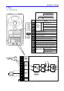
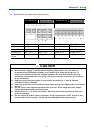
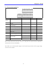
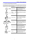
3.2 Specifications for power terminal block wiring
CI-000-C2-1P CI-001-C2-1P CI-002-C2-1P CI-003-C2-1P
Input wire size 2mm
2
2mm
2
3.5mm
2
3.5mm
2
Output wire
2mm
2
2mm
2
3.5mm
2
3.5mm
2
Ground Wire
2mm
2
2mm
2
3.5mm
2
3.5mm
2
Terminal Lug
2mm
2
,3.5 φ 2mm
2
,3.5 φ 3.5mm
2
,3.5 φ 3.5mm
2
,3.5 φ
Tightening
Torque
13kgf cm 13kgf cm 15kgf cm 15kgf cm
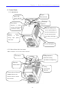
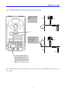
L1 L2 P P1 N
L1
L2
P P1 N
U V
W
U V W
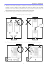
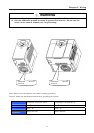
CAUTION
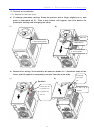
z Make sure the input power is off before wiring.
z When power supply is switched off following operation, wait at least 10
minutes after LED keypad display is off before you start working on it. If
tester is available, check the voltage between P1 and N terminals. Wiring
should be performed after verifying that input voltage in inverter DC circuitry
is all exhausted.
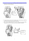
z Applying input power supply to the output terminals U, V and W causes
internal inverter damage.
z Use ring terminals with insulated caps when wiring the input power and motor
wiring.
z Do not leave wire fragments inside the inverter. Wire fragments can cause
faults, breakdowns and malfunctions.
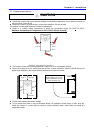
z Never short P1 or P and N terminals. Shorting terminals may cause internal
inverter damage.
z Do not install a power factor capacitor, surge suppressor or RFI filters in the
output side of the inverter. Doing so may damage these components.
18