


Chapter 12. Protective functions
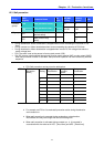
12.5 External trip signal
Group
LED
display
Description
Set
Value
Min/Max
setting
Factory
default
Unit
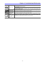
I20
[Multi-function input
terminal P1 define]
0
~ ~
I23
[Multi-function input
terminal P4 define]
18
3
I/O group
I24
[Multi-function input
terminal P5 define]
19
0/24
4
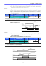
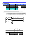
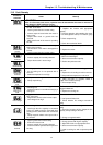
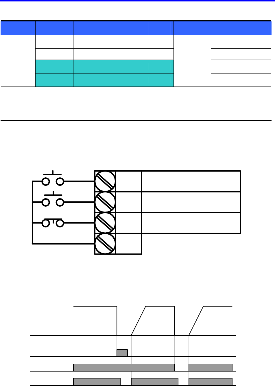
Select a terminal among P1 thru P5 to output external trip signal.
Set I23 and I24 to 18 and 19 to define P4 and P5 as External A contact and B contact.
External trip signal input A contact (N.O): This is a normally open contact input. When
a P4 terminal set to “Ext trip-A” is ON, inverter displays the fault and turns off its output.
External trip signal input B contact (N.C): This is a normally closed contact input. When
a terminal set to “Ext trip-B” is OFF, inverter displays the fault and turns off its output.
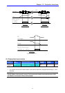
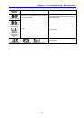
P1
P4
P5
FX : I20 = 0
N.O. : I23 = 18
CM
N.C. : I24 = 19
P4(A contact)
Frequency
Run
command
P5(B contact)
114