


44
Section 5: Maintenance & Lubrication
RCF3696, RCFM3696, RCF3610, & RCFM3610 Rotary Cutters 326-600M
12/15/15
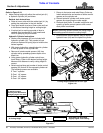
Table of Contents
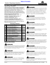
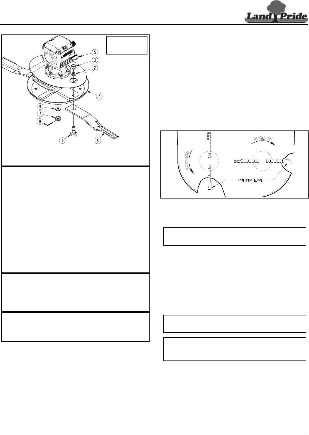
Cutter Blade Assembly
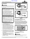
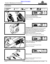
Figure 5-1
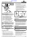
Refer to Figure 5-1 on page 44:
3. Remove access cover (#5).
4. Rotate blade bolt (#1) until aligned with access
hole.
5. Unscrew locknut (#3) to remove cutting blade (#6).
Blade bolt (#1) is keyed and will not turn freely.
6. Both blades should be sharpened at the same angle
as the original cutting edge and must be replaced or
re-ground at the same time to maintain proper
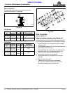
Land Pride Cutter Blade Parts
Item Part No. Part Description
318-586A BLADE BOLT KIT
(Includes items 1, 2, 3, & 4 below)
1 802-277C BLADE BOLT 1 1/8-12 x 3 7/16 WITH KEY
2 312-075D BLADE SPACER 16 GA. (.060")
2 312-082D BLADE SPACER 18 GA. (.048")
2 312-089D BLADE SPACER 20 GA. (.036")
2 312-808D BLADE SPACER 24 GA. (.024")
3 804-147C WASHER FLAT 1 HARD ASTMF436
4 803-170C NUT HEX TOP LOCK 1 1/8-12 PLATE
5 826-430H RCF3696 DISHPAN WELDMENT
5 326-429H RCF3610 DISHPAN WELDMENT
6 840-273C PLUG LP 3" ID RUBBER
7 ------------ SEE LIST OF CUTTER BLADES BELOW
35013
Use 1-11/16"
Socket Wrench
On Blade Nut #6
Land Pride List of Cutter Blades
Part No. Part Description
820-195C RCF3696 CUTTER BLADE 1/2 x 4 x 20 CCW
820-196C RCF3696 CUTTER BLADE 1/2 x 4 x 20 CW
820-137C RCF3610 CUTTER BLADE 1/2 x 4 x 25 CCW
820-112C RCF3610 CUTTER BLADE 1/2 x 4 x 25 CW
Optional Low Lift Cutter Blades
820-210C RCF3696 BLADE 1/2X4X20.5 LL CCW
820-211C RCF3696 BLADE 1/2X4X20.5 LL CW
820-193C RCF3610 BLADE 1/2X4X25 LL CCW
820-209C RCF3610 BLADE 1/2X4X25 LL CW
balance. The following precautions should be taken
when sharpening blades:
a. Do not remove more material than necessary.
b. Do not heat and/or pound out a cutting edge.
c. Do not grind blades to a razor edge. Leave a blunt
cutting edge approximately 1/16" thick.
d. Always grind cutting edge so end of blade remains
square to cutting edge and not rounded.
e. Do not sharpen back side of blade.
f. Both blades should weigh the same after
sharpening with not more than 1 1/2 oz.
difference.
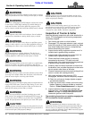
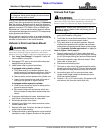
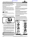
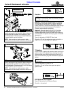
Blade Positioning and Rotational Directional
Figure 5-2
Refer to Figure 5-2:
7. Make certain when installing cutter blades that the
blades on one spindle is positioned 90 degrees to the
blades on the other spindle as shown in Figure 5-2.
8. Carefully check cutting edges of blades in relation to
blade carrier rotation to ensure correct blade
placement. Blade rotation is counterclockwise on the
left side and clockwise on the right side. Airfoil (lift)
must be oriented towards the top of the deck.
Refer to Figure 5-1:
9. Insert blade bolt (#1) through blade (#6), dish
pan (#4), and flat washer (#2). Secure blade with a
new locknut (#3) and torque to 450 ft-lbs.
10. If replacing dishpan (#4), castle nut (#7) on gearbox
output shaft should be torqued to 550 ft-lbs. minimum
and secured with cotter pin (#8) with both legs bent
opposite directions around the nut.
11. Replace access rubber plug (#5) and reconnect main
driveline to tractor PTO shaft.
CCW
CC
IMPORTANT: Blades are to be timed at 90
o
from one
dishpan to the other or they could be damaged.
IMPORTANT: Examine blade bolts (#1) and
washers (#3) for excessive wear and replace if worn.
IMPORTANT: Locknuts can loose their ability to lock
properly once removed. Always use a new locknut
when installing blades.