


22
Section 1: Assembly & Set-Up
RCF3696, RCFM3696, RCF3610, & RCFM3610 Rotary Cutters 326-600M
12/15/15
Table of Contents
Pull-Type Assembly & Set-Up
The following pages are “Assembly & Set-Up
Instructions” for Pull-Type cutters. Not all instructions
apply to your cutter. See “3-Point Assembly & Set-Up”
on page 12 and “Semi-Mount Assembly & Set-Up” on
page 17.
Tailwheel Lift Options
The cutter is shipped with an attached ratchet jack or
hydraulic cylinder. Hydraulic cylinder option includes
hydraulic hose, stroke control spacers and quick
disconnect couplings. The ratchet jack option is lever
operated at the jack.
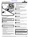
Axle Assembly
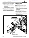
Refer to Figure 1-18:
There are several hydraulic cylinder/ratchet jack
mounting lugs (#4) that can be installed on axle (#3).
Make sure this cutter is equipped with the correct lug and
that the notch in the lug is located on the axle properly.
See your nearest Land Pride dealer if mounting lug is not
installed correctly or is the wrong mounting lug.
NOTE: If preferred, rear guards may be assembled
before tailwheels. See “Section 2: Assembly of
Optional Equipment” on page 28 for chain or
rubber rear guard assembly instructions.
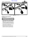
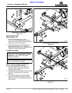
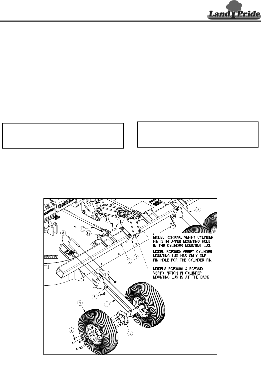
Pull-Type Tailwheel Assembly (Dual Laminated Tires Shown)
Figure 1-18
33949
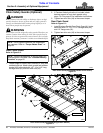
1. Verify mounting lug is correct as follows:
• Models RCF(M)3696 & RCF(M)3610: Notch in
cylinder mounting lug (#4) must be positioned at
the back.
• Model RCF(M)3696: The rod end cylinder pin
must be in upper mounting hole in mounting
lug (#4).
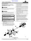
• Model RCF(M)3610: The cylinder mounting lug
(#4) has only one pin hole for the cylinder pin.
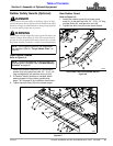
2. Attach left and right-hand tailwheel arms (#1 & #2) to
axle (#3) with 5/8"-11 U-bolts (#8) and hex flange lock
nuts (#6). Do not tighten lock nuts.
3. Adjust tailwheel arms to desired locations. Tighten
lock nuts (#6) to the correct torque.
4. Attach tailwheels (#9) to axle hubs (#5) with
1/2"-20 x 5/8" high hex nuts (#7). Tighten 1/2" hex nuts
to the correct torque in a crisscross pattern.
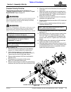
5. If leveling rods (#10) were removed while uncrating
the unit, reattach them to axle (#3) as shown with
clevis pins (#11), flat washers (#12), and cotter
pins (#13). Bend one or more legs of cotter pins to
secure it in place.
NOTE: Pull-Type cutters are supplied with either
two single tailwheels or four tailwheels arranged in
dual tailwheel fashion. All tailwheels are shipped
loose and must be mounted to the axle hubs (#5).