


13
Section 1: Assembly & Set-Up
12/15/15
RCF3696, RCFM3696, RCF3610, & RCFM3610 Rotary Cutters 326-600M
Table of Contents
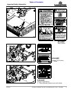
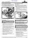
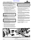
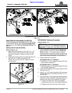
RCF(M)3610 3-Point Tailwheel Assembles
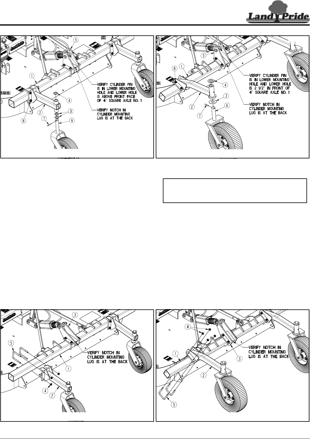
Figure 1-7
35003
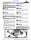
RCF(M)3610 Model With 15" Tailwheel Assembly
35025
)
RCF(M)3610 Model With 21" Tailwheel Assembly
35203
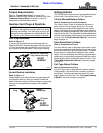
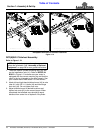
RCF(M)3696 Model With 15" Tailwheel Assembly
35204
RCF(M)3696 Model With 21" Tailwheel Assembly
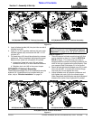
RCF(M)3696 3-Point Tailwheel Assembles
Figure 1-6
Refer to Figure 1-7:
1. There are several cylinder mounting lugs (#3) that
can be installed on axle (#1). Refer to NOTES IN
BOLD in Figure 1-7 to make sure your cutter is
equipped with the correct mounting lug and that the
notch in the lug is located on the axle properly. See
your nearest Land Pride dealer if it is not correct.
2. Attach left and right-hand tailwheel arms (#2) to axle
tube (#1) with 5/8"-11 U-bolts (#5) and hex flange
lock nuts (#4). Do not tighten lock nuts.
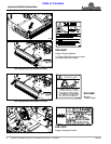
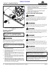
3. Adjust tailwheel arms to customer preference and
then tighten lock nuts (#4) to the correct torque.
When completed, the tailwheel arms should be equal
distance from center line of hydraulic lift cylinder.
NOTE: If preferred, rear guards may be assembled
before the tailwheels. See “Assembly of Optional
Equipment” on page 28 for rear guard instructions.
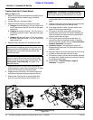
3. Insert tailwheel spindle (#6) into pivot tube on end of
tailwheel arm (#2).
4. Install 2 1/4" O.D. machine washers (#4) over each
tailwheel spindle (#6) and secure with 3/8" x 2 1/2"
roll pins (#7).
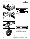
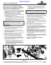
5. Tail wheel arms (#2) should be adjusted to customer
preference. When completed, they should be equal
distance from center line of hydraulic lift cylinder.
a. Loosen hex flange lock nuts (#8) and adjust
tailwheel arms (#2) in or out to desired locations.
b. Retighten lock nuts (#8) to the correct torque.
RCF(M)3610 Tailwheel Assembly
These instructions apply only to 10' models with rear axle
hydraulic lift. If hydraulics are not included with your
cutter, skip to “Driveline Installation” on page 14.