


20
Section 1: Assembly & Set-Up
RCF3696, RCFM3696, RCF3610, & RCFM3610 Rotary Cutters 326-600M
12/15/15
Table of Contents
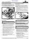
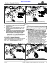
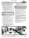
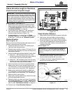
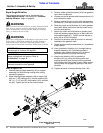
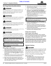
Tractor Hook-Up To Semi-Mount
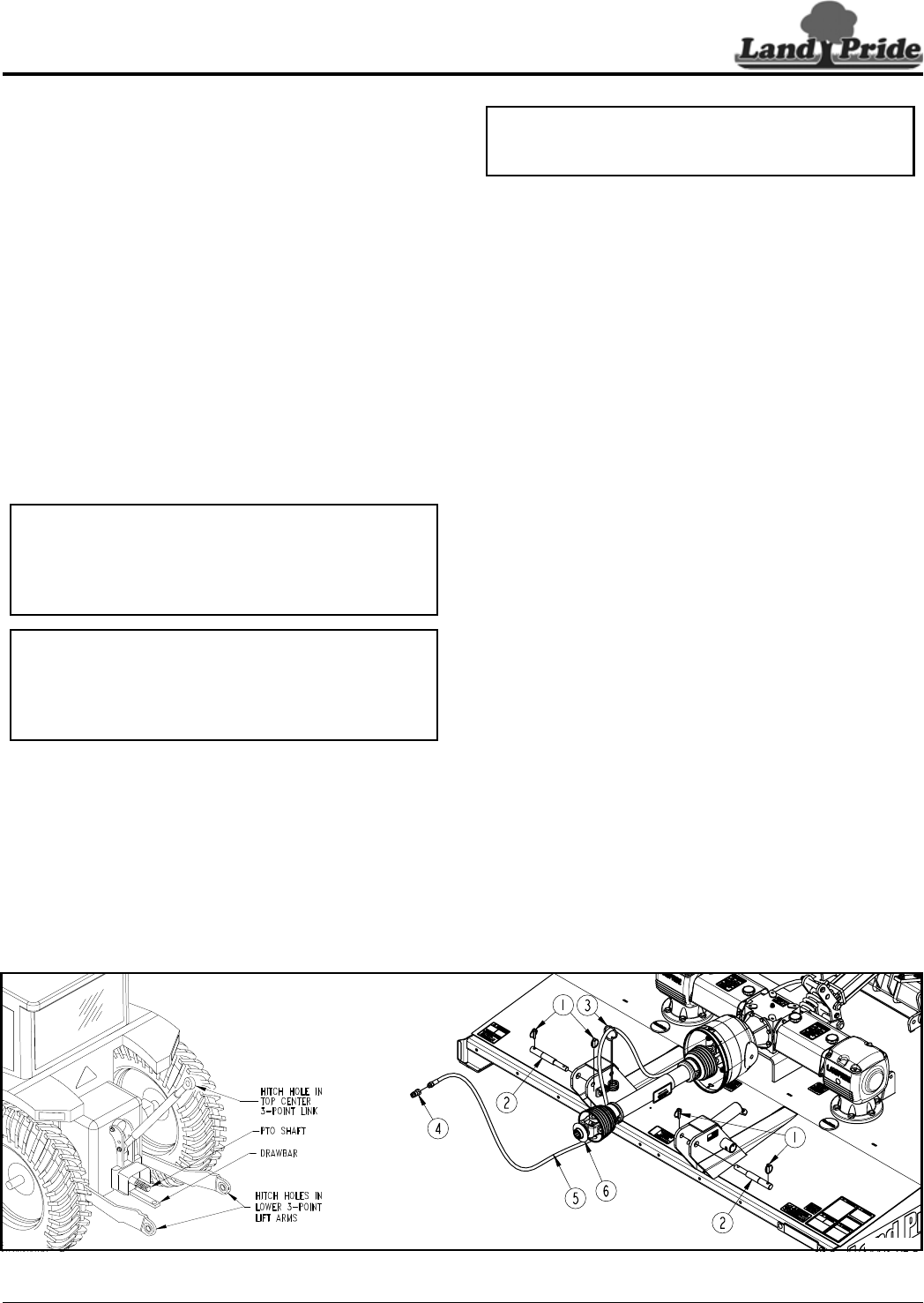
Refer to Figure 1-15:
1. Make sure you have read and follow all Safety Alerts
and Important Notes listed on page 19 before
continuing.
2. Locate cutter on a flat level surface.
3. Determine hitch category of tractor to be used:
a. Category I tractors will have 7/8" dia. holes in the
lower 3-point arms and 3/4" dia. hole in the upper
center link.
b. Category II tractors will have 1 1/8" dia. holes in
the lower 3-point arms and 1" dia hole in the upper
center link.
c. Category III tractor will have 1 7/16" dia. holes in
the lower 3-point arms and 1 5/16" dia. hole in the
upper center link.
4. Remove lower linchpins (#1) and hitch pins (#2).
5. Slowly back tractor to cutter while using tractor’s
3-point hydraulic control lever to align holes in lower
3-point lift arms with clevis hitch pin holes.
6. Engage tractor park brake, shut tractor engine off,
and remove key before dismounting from tractor.
7. Attach lower 3-point arms to clevises with hitch
pins (#2). Secure hitch pins with linchpins (#1).
NOTE: The lower 3-point arms on a Cat. II tractor
are positioned outside the clevis hitch plates when
hooking-up to the RCF(M)3696. All other hook-ups
will require the arms to be positioned inside the
clevis hitch plates.
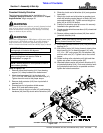
NOTE: The spring hose loop (#3) may need to be
moved if using a Quick Hitch and the Quick Hitch
interferes with spring hose loop mounting bolt. See
“Spring Hose Loop Assembly” on page 12 for
alternate location.
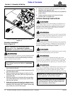
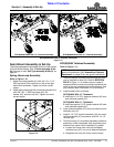
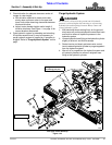
8. Slowly engage tractor 3-point lift lever to raise cutter
until gearbox shaft is in-line (level) with tractor PTO
shaft.
9. Support cutter deck at this height with support jacks
or blocks to keep cutter from drifting down.
10. Place gear selector in park, set park brake, shut
tractor off and remove switch key.
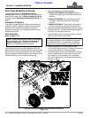
11. Pull back on driveline yoke collar (#6) and push
driveline yoke onto tractor PTO shaft. Release pull
collar and continue to push driveline yoke forward
until pull collar locks in place.
12. Pull on both ends of driveline to make sure it is
secured to tractor and gearbox shafts. If driveline
yoke will not lock in place, skip to “Check Driveline
Length & Clearance” on page 21.
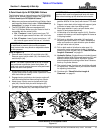
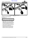
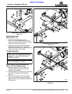
13. Hydraulic Option: Thread hydraulic hose (#5)
through spring hose loop (#3) and attach to tractor
hydraulic outlet.
14. Manually adjust one of the lower 3-point lift arms up
or down to level the cutter from left to right.
15. The tractor’s lower 3-point arms should be adjusted
for lateral float. Please consult your tractor’s manual
for adjusting instructions.
16. Continue with “Check Driveline Length &
Clearance” on page 21.
IMPORTANT: The tractor’s PTO shaft and cutter
gearbox shaft must be aligned and level with each
other when hooking-up the driveline to the tractor.
33952
37298
Semi-Mount Tractor Hook-Up
Figure 1-15