


12
Section 1: Assembly & Set-Up
RCF3696, RCFM3696, RCF3610, & RCFM3610 Rotary Cutters 326-600M
12/15/15
Table of Contents
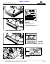
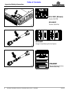
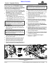
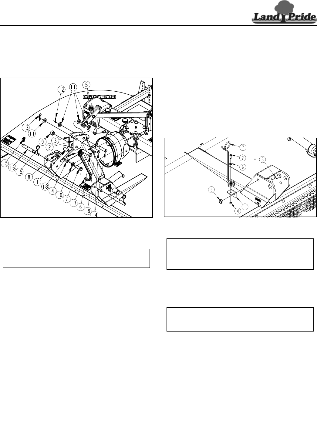
Spring Hose Loop Assembly
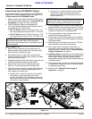
Refer to Figure 1-5:
3-Point mounted cutters with hydraulic cylinder option are
shipped with a spring hose loop. Skip to “Driveline
Installation” on page 19 if hydraulics are not included.
1. Attach mounting bracket (#1) with 3/4"-10 x 1 1/2"
GR5 cap screw (#3) and lock nut (#5) to the outside
of the right-hand clevis as shown. Tighten lock nut to
the correct torque.
2. Attach spring hose loop (#7) to mounting bracket (#1)
with 3/8"-16 x 1" GR5 cap screw (#2), flat washer
(#6), and lock nut (#4). Tighten lock nut to the correct
torque.
RCF(M)3610 3-Point Spring Hose Loop Mount
Figure 1-5
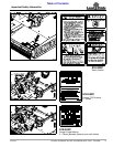
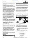
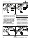
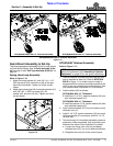
RCF(M)3696 Tailwheel Assembly
These instructions apply only to 96" models with rear
axle hydraulic lift. If hydraulics are not included with your
cutter, skip to “Driveline Installation” on page 14.
Refer to Figure 1-6:
1. There are several cylinder mounting lugs (#5) that
can be installed on axle (#1). Refer to NOTES IN
BOLD in Figure 1-6 to make sure your cutter is
equipped with the correct mounting lug and that the
notch in the lug is located on the axle properly. See
your nearest Land Pride dealer if it is not correct.
2. Install washers (#3) as follows:
RCF(M)3696 With 15" Tailwheels
• Install two 2 1/4" O.D. machine washers (#3) onto
each tailwheel spindle (#6).
RCF(M)3696 With 21" Tailwheels
• Install one special 4" O.D. harden washer (#3) onto
each tailwheel spindle (#6).
35005
NOTE: The RCF(M)3696 & RCFM3696 3-point
cutters are shipped with tailwheels factory mounted.
The RCF3610 & RCFM3610 are shipped with
tailwheels not assembled to the unit.
NOTE: If preferred, rear guards may be assembled
before the tailwheels. See “Assembly of Optional
Equipment” on page 28 for rear guard instructions.
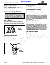
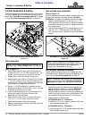
3-Point Assembly & Set-Up
The following pages are Assembly & Set-Up Instructions
for 3-point cutters. Not all instructions will apply to your
cutter. See “Semi-Mount Assembly & Set-Up” on page
17 and “Pull-Type Assembly & Set-Up” on page 22.
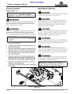
3-Point Hitch Assembly (RCF(M)3696 Shown)
Figure 1-4
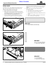
Hitch Assembly
Refer to Figure 1-4:
1. Attach Right-hand A-Frame (#3) to hitch plate as
shown with 7/8"-9 x 2 1/2" GR5 cap screw (#7), flat
washer (#10), bushing (#4), and nylock nut (#8).
2. Repeat step 1 for the left-hand A-Frame (#2).
3. Attach short braces (#5) to A-Frames (#2 & #3) with
1" x 3 3/16" clevis pin (#14), three flat washers (#11),
and cotter pin (#12) as shown. Bend one or more legs
of the cotter pin to keep it from falling out.
4. Secure 1 1/4" OD. bushing (#1) between the two
A-Frame hitch plates (#2 & #3) with 1"-8 x 4 1/2" cap
screw (#6) and nylon lock nut (#9).
5. Install remaining clevis pin (#14), flat washer (#11)
and hairpin cotter (#13) to the A-Frame hitch
assembly (#2 & #3) as shown.
6. Attach driveline hook (#17) to A-frame (#2) using
5/16"-18 x 1 1/4" bolt (#18) and lock nut (#19).
7. Tighten all hardware to the correct torque.
8. Remove shipping bolt and nuts in hitch pin (#16) and
insert linchpins (#15).
33942a
NOTE: Do not tighten hardware until assembly is
complete. See “Torque Values Chart” on page 56.