


21
Section 1: Assembly & Set-Up
12/15/15
RCF3696, RCFM3696, RCF3610, & RCFM3610 Rotary Cutters 326-600M
Table of Contents
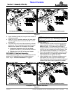
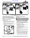
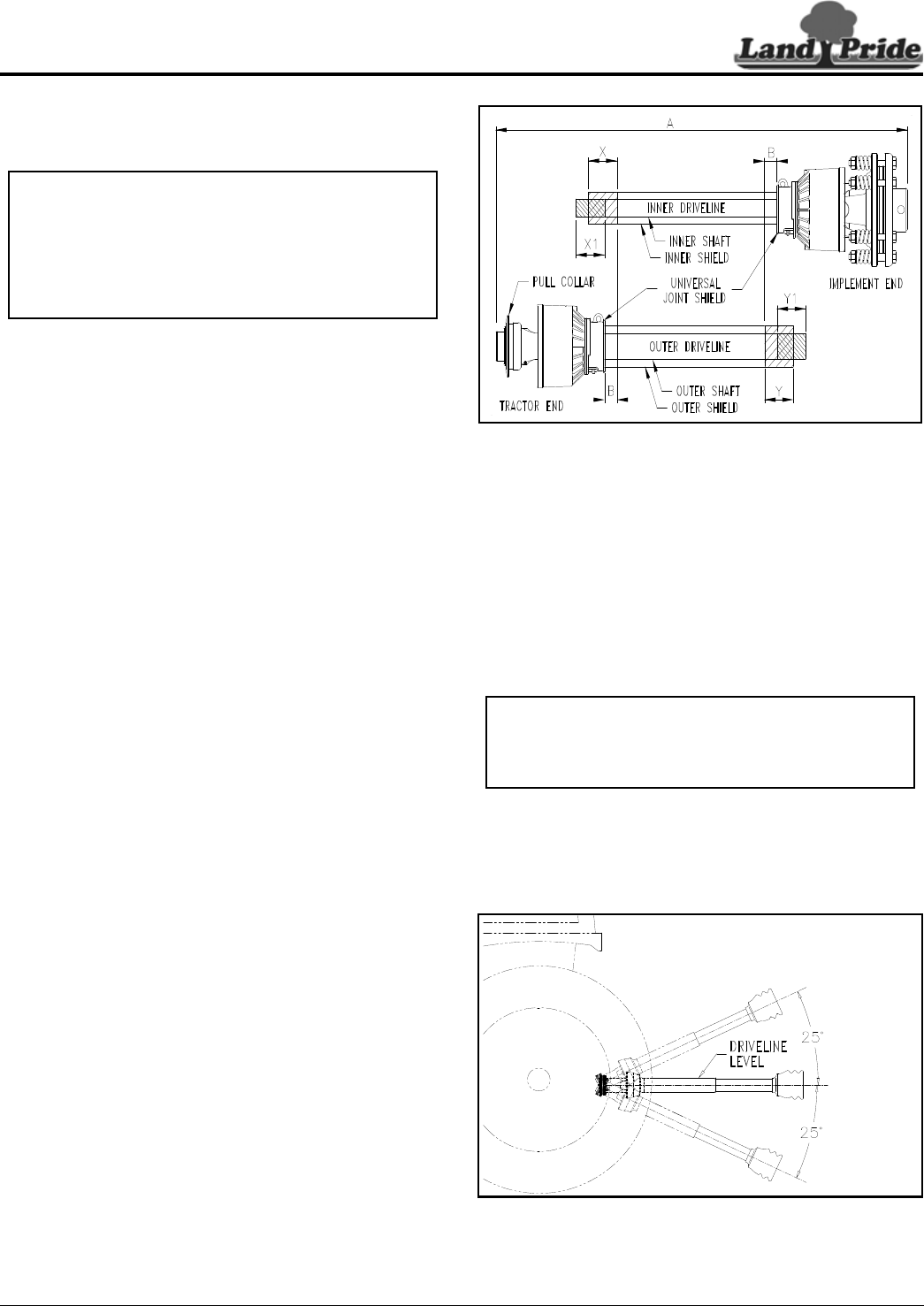
Check Driveline Length & Clearance
Check Driveline Collapsible Length
Refer to Figure 1-14 & Figure 1-17:
1. Make sure driveline is properly installed and level
before checking driveline collapsible length. Refer
to “Driveline Installation” instructions on page 14 or
“Driveline Installation” on page 19
2. With driveline level, measure 1" (“B” dimension)
back from universal joint shield to end of outer
driveline shield as shown in Figure 1-16.
3. If measurement is 1" or more, skip to “Check
Driveline Clearance” on this page. If measurement
is less than 1", continue with “Shorten Driveline”.
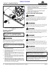
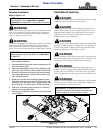
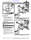
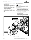
Shorten Driveline
Refer to Figure 1-16:
Be sure to first check driveline collapsible length above. If
required, shorten driveline as follows:
1. Unhook driveline from tractor PTO shaft and pull
outer and inner drivelines apart.
2. Reattach outer driveline to tractor PTO shaft. Pull on
inner and outer drivelines to be sure universal joints
are properly secured.
3. Hold inner and outer drivelines parallel to each other:
a. Measure 1" (“B” dimension) back from outer
driveline universal joint shield and make a mark at
this location on the inner driveline shield.
b. Measure 1" (“B” dimension) back from the inner
driveline universal joint shield and make a mark at
this location on the outer driveline shield.
4. Remove driveline from tractor and gearbox shafts.
5. Measure from end of inner shield to scribed mark
(“X” dimension). Cut off inner shield at the mark. Cut
same amount off the inner shaft (“X1” dimension).
6. Measure from end of outer shield to scribed mark
(“Y” dimension). Cut off outer shield at the mark. Cut
same amount off the outer shaft (“Y1” dimension).
7. Remove all burrs and cuttings.
8. Apply multi-purpose grease to the inside of the outer
shaft and reassemble driveline.
9. Reattach driveline to cutter and tractor. For detailed
instructions, see steps 11 to 13 under “3-Point Hook-
Up to RCF(M)3696 Cutters” on page 15 or steps 11
and 12 under “Semi-Mount Hook-Up” on page 20.
10. Continue with “Check Driveline Clearance”.
IMPORTANT: A driveline that is too long can bottom
out causing structural damage to tractor and cutter.
Always check driveline collapsed length during initial
setup, when connecting to a different tractor, and
when alternating between using a quick hitch and a
standard 3-point hitch. More than one driveline may
be required to fit all applications.
Driveline Shortening
Figure 1-16
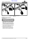
Check Driveline Clearance
1. Make certain driveline yokes are properly attached.
2. Start tractor and raise cutter up just enough to
remove support blocks. Remove support blocks.
3. Slowly and carefully raise cutter to ensure drawbar,
tires, and other equipment on the tractor do not
contact cutter frame. Move or remove drawbar if it
interferes with cutter.
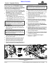
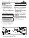
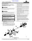
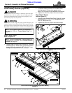
Refer to Figure 1-17:
4. Raise and lower implement to find maximum
extended driveline length. Check to make certain
driveline does not exceed 25
o
up or down.
5. If needed, set tractor 3-point lift height to keep
driveline from exceeding 25
o
up.
Maximum PTO Driveline Movement During Operation
Figure 1-17
22311
IMPORTANT: Avoid premature driveline breakdown.
A driveline that is operating must not exceed an
angle of 25 degrees up or down while operating 3-
point lift.
24872