


24
Section 1: Assembly & Set-Up
RCF3696, RCFM3696, RCF3610, & RCFM3610 Rotary Cutters 326-600M
12/15/15
Table of Contents
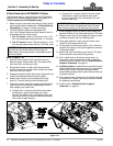
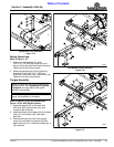
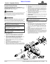
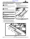
3. Remove rubber protective sleeve (#13) from gearbox
input shaft and discard.
4. Unsnap one end of gearbox shield access doors (#1)
and rotate doors open.
5. Remove conical dog pin or bolts (#6) and fastening
hardware (#7) from slip-clutch end of driveline (#11).
6. Slide slip-clutch end of driveline (#11) onto gearbox
input shaft. Make certain that the slip-clutch is fully
onto the shaft splines.
7. Attach slip-clutch end of driveline to gearbox input
shaft with existing conical dog pin or bolts (#6) and
removed hardware (#7). Tighten conical dog pin or
bolts (#6) to 45-50 ft-lb torque.
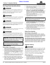
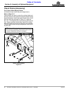
8. Push/pull on driveline yoke to be sure it is securely
fastened to the gearbox shaft.
9. Rotate gearbox shield access doors (#1) closed and
snap in place.
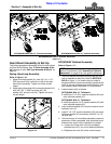
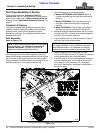
10. Insert jackshaft of driveline (#11) through bearing
support assembly (#2). Pull bearing support
assembly fully against driveline (#11) to extend
jackshaft splines fully through the bearing.
11. Install main driveline (#12) to jackshaft of
driveline (#11) by pulling on locking collar and
pushing driveline yoke forward onto the jackshaft
until locking collar has locked in place. Make certain
locking collar has engaged by pulling on the main
driveline.
12. Tighten set screw in bearing locking collar (#2).
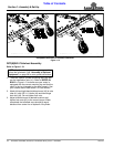
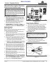
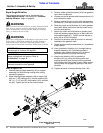
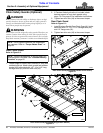
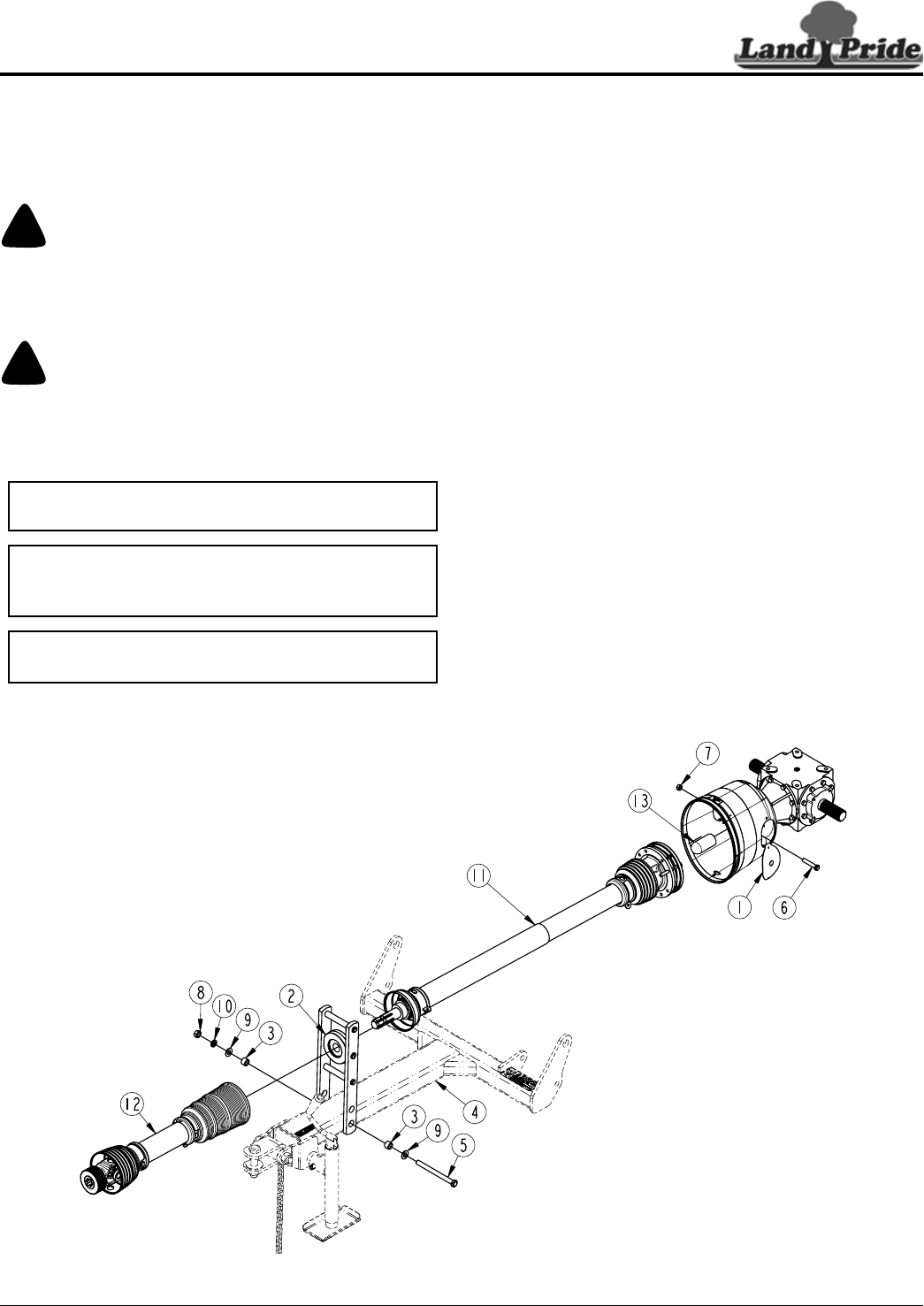
Equal Angle Hitch Assembly
Figure 1-22
33946
Equal Angle Driveline
The following instructions are for installation of an
“Equal Angle Driveline”. Instructions for “Constant
Velocity Driveline” begin on page 25.
!
WARNING
Make certain all driveline yokes are securely fastened at both
ends. A loose yoke can work free allowing the driveline to
rotate uncontrollably causing machine damage and bodily
injury or death to anyone nearby.
!
WARNING
Do not use a PTO adapter. A PTO adapter will increase strain
on the tractor’s PTO shaft resulting in possible damage to
shaft and driveline. It will also defeat the purpose of the
tractor’s master shield and could cause bodily injury or death.
Refer to Figure 1-22:
1. Position bearing flange assembly (#2) on tongue
assembly (#4) with bearing locking collar facing
towards the gearbox.
2. Attach bearing flange assembly (#2) to tongue (#4)
with two 1" OD bushings (#3), two flat washers (#9),
5/8"-11 x 7 1/2" bolt (#5), lock washer (#10), and hex
nut (#8). Tighten hex nut to the correct torque.
IMPORTANT: Maximum equal angle driveline
turning angle is limited to 35 degrees.
IMPORTANT: The drivelines must be lubricated
before putting them into service. Refer to
“Lubrication” on page 49.
NOTE: .Make sure bearing locking collar is facing
rearward toward the cutter gearbox.