


SECTION 4.2
OPERATIONAL ANALYSIS
PART 4
DC CONTROL
Page 4.2-1
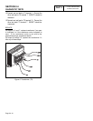
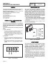
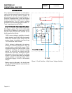
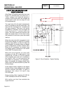
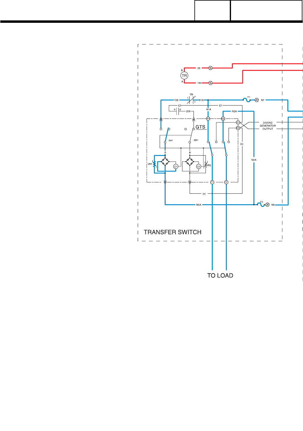
Figure 1. Circuit Condition - Utility Source Voltage Available
INTRODUCTION
This "Operational Analysis" is intended to
familiarize the service technician with the
operation of the DC control system on
prepackaged units with air-cooled engine. A
thorough understanding of how the system
works is essential to sound and logical
troubleshooting. The DC control system
illustrations on the following pages include a "V-
Type" prepackaged transfer switch.
UTILITY
SOURCE
VOLTAGE
AVAILABLE
See Figure 1, above. The circuit condition with
the AUTO-OFF-MANUAL switch set to AUTO
and with "Utility" source power available can be
briefly described as follows:
"Utility" source voltage is available to transfer
switch terminal lugs N1/N2. With the transfer
switch main contacts at their "Utility" side, this
source voltage is available to terminal lugs
T1/T2 and to the "Load" circuits.
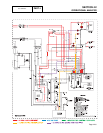
"Utility" voltage is delivered to the primary
winding of a sensing transformer (TX), via
transfer switch wires N1/N2, fuses F1/F2,
connected wiring, and Control Panel "Utility
1/Utility 2" terminals. A resultant voltage
(about 16 volts AC) is induced into the
transformer secondary windings and then
delivered to the circuit board via Wires
224/225. The circuit board uses this reduced
"Utility" voltage as sensing voltage. Wires
224A/225A supply 16 VAC to the battery
charger.
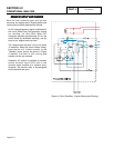
Battery output is delivered to the circuit board
with the AUTO-OFF-MANUAL switch (SW1) set
to AUTO, as shown.