


SECTION 2.4
DIAGNOSTIC TESTS
AC GENERATORS
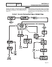
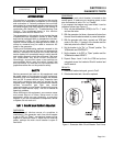
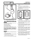
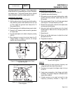
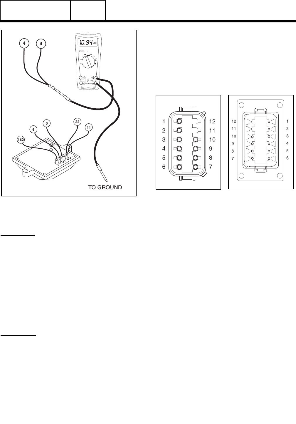
Figure 4. Field Boost Test Points
TEST
7:
TESTING
THE
STATOR
WITH
A
VOM
DISCUSSION:
A Volt-OHM-Milliammmeter (VOM) can be used to test the
stator windings for the following faults:
❏ An open circuit condition
❏ A "short-to-ground" condition
❏ A short circuit between windings
Note: The resistance of stator windings is very low.
Some meters will not read such a low resistance, and
will simply indicate CONTINUITY. Recommended is a
high quality, digital type meter capable of reading very
low resistances.
PROCEDURE:
1. Disconnect stator leads 11 and 44 from the main circuit
breaker.
2. Disconnect stator leads 22 and 33 from the neutral
connection separate the leads.
3. Disconnect Connector C2 from the side of the control
panel (C2 is the closest to the back panel).
4. Make sure all off the disconnected leads are isolated
from each other and are not touching the frame during
the test.
5. Set a VOM to its "R x 1" scale and zero the meter.
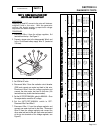
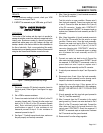
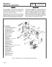
6. Refer to Figure 5 for pin locations of Connector C2. Use
a large paper clip or similar metallic object to access
pins in connector C2.
Note: Pins 9, 10, 11 & 12 are not used for this test.
7. Connect one test lead to stator lead Wire 11. Connect
the other test lead to stator lead Wire 22 (power
winding). Note the resistance reading and compare to
the specifications on Page 2.
8. Connect one test lead to stator lead Wire 33. Connect
the other test lead to stator lead Wire 44 (power
winding). Note the resistance reading and compare to
the specifications on Page 2.
9. Connect one test lead to Pin 1. Connect the other test
lead to Pin 2 (battery charge winding). Note the
resistance reading, compare to specifications on Page 2.
10.Connect one test lead to Pin 3. Connect the other test
lead to Pin 4 (engine run winding). Note the resistance
reading, compare to specification Page 2.
11.Connect one test lead to Pin 5. Connect the other test
lead to Pin 6 (power winding-sense leads). Note the
resistance reading, compare to specification Page 2.
12.Connect on test lead to Pin 7. Connect the other test
lead to Pin 8 (excitation winding). Note the resistance
reading, compare to specification Page 2.
PART 2
Page 2.4-5
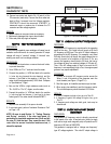
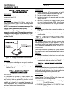
Figure 5. C2 Connector
Pin Locations
(Female Side)
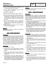
Figure 6. C2 Connector
Pin Locations
(Male Side)