


SECTION 3.2
OPERATIONAL ANALYSIS
V-TYPE PREPACKAGED
TRANSFER SWITCHES
PART 3
Page 3-2.4
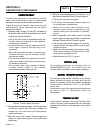
TRANSFER
TO
STANDBY
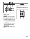
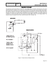
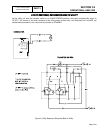
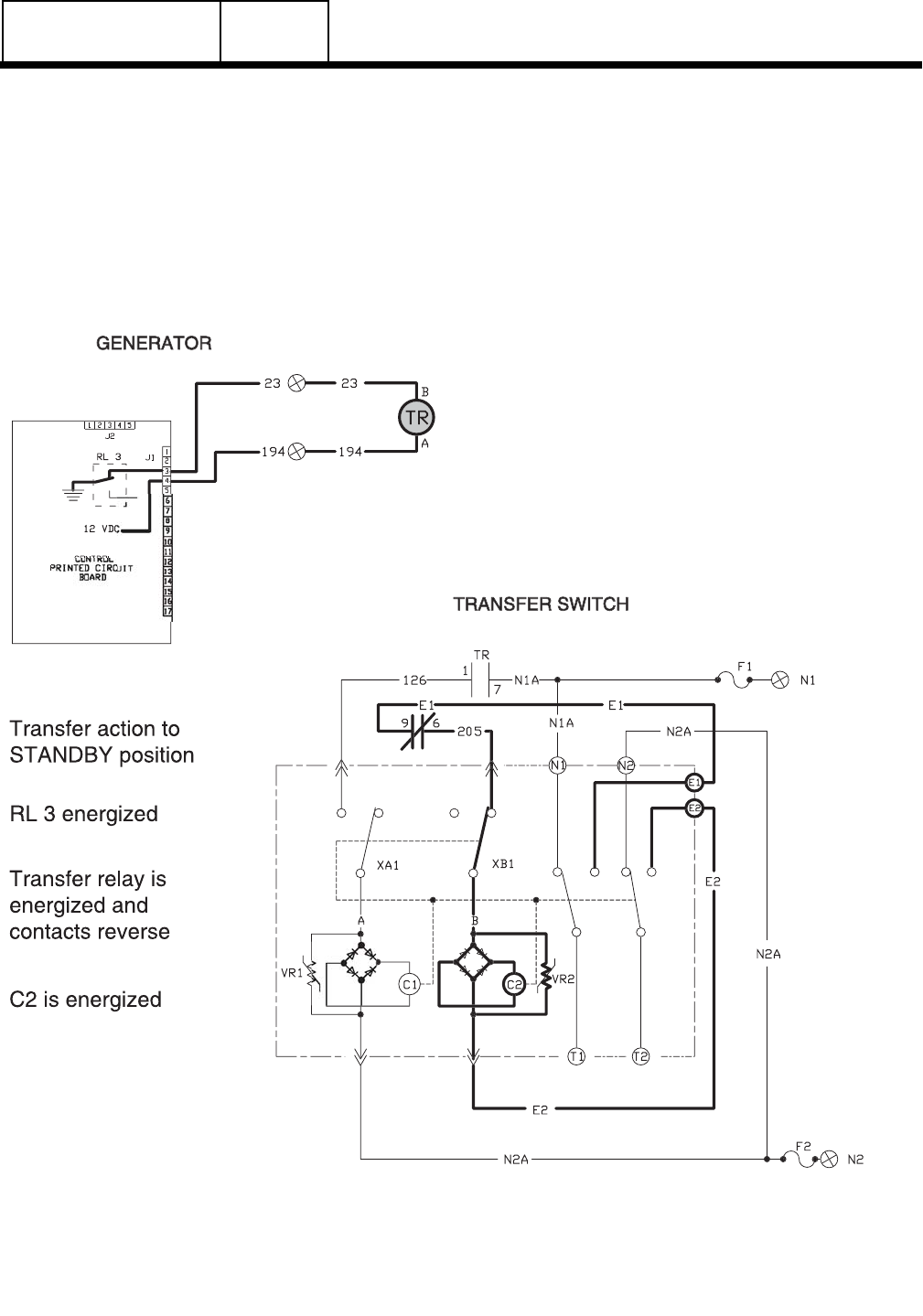
The generator circuit board delivers 12 volts DC to the transfer relay, via terminal 194 and back to the circuit
board via terminal 23. However, circuit board action holds the Wire 23 circuit open and the transfer relay remains
de-energized. On generator startup, an "engine warm-up timer" on the generator circuit board starts timing. When
that timer has timed out, circuit board action completes the Wire 23 circuit to ground. The transfer relay then
energizes, its normally open contacts close, and standby source voltage is delivered to the standby closing coil
via Wires E1 and E2, the transfer relay (TR) contacts, limit switch (XB1), Wire "B". and a bridge rectifier. The
standby closing coil energizes and the main contacts actuate to their "Standby" side.
Figure 4. Transfer Action to Standby Position