


MAJOR
DISASSEMBLY
STATOR/ROTOR/ENGINE REMOVAL:
For stator removal, follow Steps 1-14. For rotor
removal, follow Steps 1-15. For Engine removal follow
Steps 1-16.
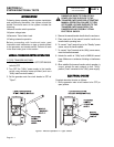
1. Remove door.
2. Set the AUTO-OFF-MANUAL switch to OFF. Disconnect
battery cables. Remove Fuse F1. Remove the utility
power source to the generator. Turn off fuel supply to
the generator.
3. Remove Control Panel Cover: Using a 10 mm socket,
remove the control panel cover. Remove two nuts
located on back panel using a 7mm socket. Remove
two control panel screws.
4. Disconnect Stator Leads/Connectors: Remove the
stator leads (Wire 11 and Wire 44) from the main circuit
breaker. Remove the stator leads (Wire 22 and Wire 33)
from the neutral lug. Unplug connectors C1 and C2 from
the control panel. For control panel removal only,
remove Wires N1/N2 and Wires 23/194 from the terminal
strip, and the ground and neutral wires from the control
panel.
5. Disconnect Fuel Hoses: Remove the two fuel hoses at
the air box assembly. Some models are equipped with
an additional third fuel hose. Remove it also if equipped.
Pull hoses back into the battery compartment. For
control panel removal only remove WireNos. 0 and 14
from the fuel solenoid.
6. Remove Front and Back Exhaust Enclosure Covers:
Using a 10mm socket, remove the five bolts and four
nuts from the exhaust covers. Remove the covers.
Remove the nut and bolt attaching to the roof left side
folding support and bottom support bracket.
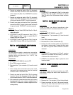
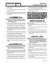
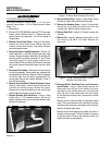
7. Remove Exhaust Side Enclosure: Using a 10mm
socket with a 2 1/2” extension remove the four (4)
bottom enclosure bolts, and six (6) side enclosure bolts.
Remove the enclosure.
Figure 1. Exhaust Side Enclosure Removed
8. Remove Exhaust Pipe: Using a 13mm socket, loosen
the exhaust clamp and remove the exhaust pipe.
9. Remove Fan Housing Cover: Using a 10 mm socket,
remove the six (6) bolts from each side of the fan
housing cover. Remove the fan housing cover.
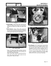
10.Remove Rotor Bolt: Using a 9/16 socket, remove one
rotor bolt.
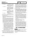
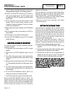
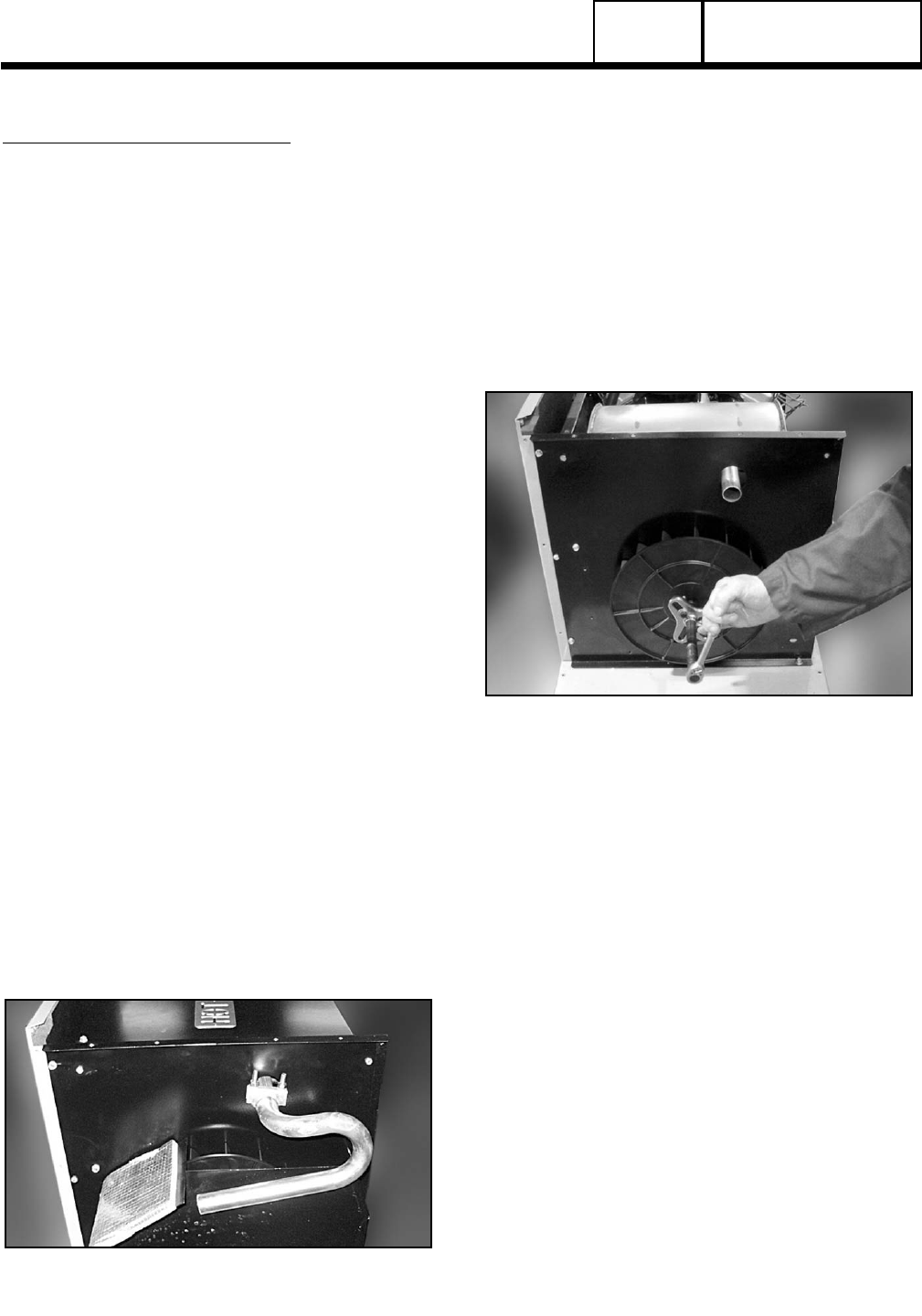
11.Remove Fan:
Attach a steering wheel puller to the
fan using two (2) M8 X 1.25 bolts. Remove fan
from rotor.
Figure 2. Using a Steering Wheel Puller to
Remove Fan From Rotor
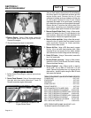
12.Remove Muffler Box/Side Cover and Alternator
panel Divider: Using a 10mm socket, remove the
three bolts from the top of the muffler box cover
that attach to the muffler side cover, and two bolts
from the side of the muffler box cover that attach
to the alternator divider plate. Remove the muffler
box cover.
Remove the four bolts that attach the alternator divider
panel. Three are connected on the left side to the back
enclosure panel, and one is connected to the enclosure
base on the bottom right corner.
Remove the two bolts attaching the muffler side cover to
the back enclosure panel. They are located in the center
of the back panel. Remove the alternator panel and
muffler side cover as an assembly.
PART 6
DISASSEMBLY
SECTION 6.1
MAJOR DISASSEMBLY
Page 6.1-1