


SECTION 3.1
DESCRIPTION & COMPONENTS
TRANSFER
RELAY
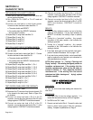
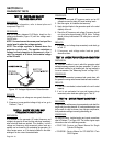
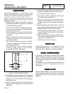
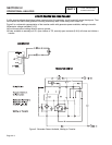
Transfer relay operation is controlled by a circuit
board. That circuit board is a part of a control panel
assembly, mounted on the standby generator set.
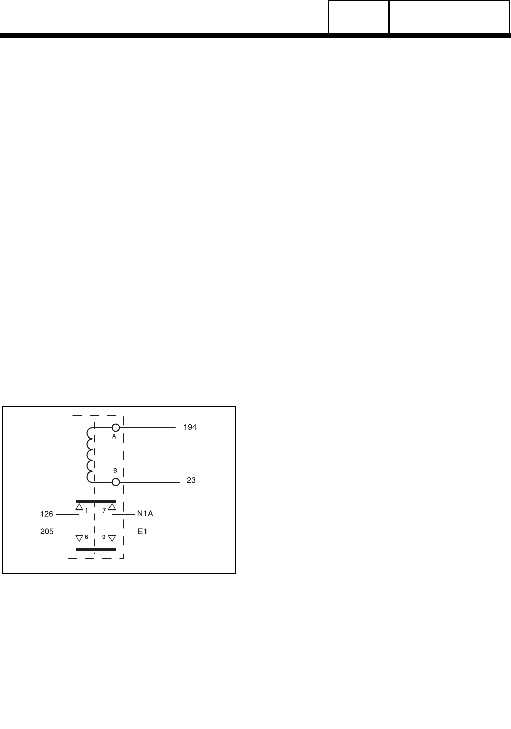
Figure 5 shows the transfer relay pictorially and
schematically. Relay operation may be briefly
described as follows:
1. Generator battery voltage (12 volts DC) is available to
the transfer relay coil from the generator circuit board,
via Wire 194 and relay terminal A.
a.The 12 volts DC circuit is completed through the
transfer relay coil and back to the generator
circuit board, via Wire 23.
b.Circuit board action normally holds the Wire 23
circuit open to ground and the relay is de-
energized.
c.When de-energized, the relay’s normally open
contacts are open and its normally-closed
contacts are closed.
d.The normally-closed relay contacts will deliver
utility source power to the utility closing circuit of
the transfer mechanism.
e.The normally open relay contacts will deliver
standby source power to the transfer
mechanism’s standby closing circuit.
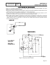
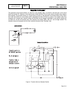
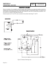
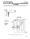
Figure 5. Transfer Relay Schematic
2. During automatic system operation, when the generator
circuit board "senses" that utility source voltage has
dropped out, the circuit board will initiate engine
cranking and startup.
3. When the circuit board "senses" that the engine has
started, an "engine warm-up timer" on the circuit board
starts timing.
4. When the "engine warm-up timer" has timed out, circuit
board action completes the Wire 23 circuit to ground.
a.The transfer relay then energizes.
b.The relay’s normally-closed contacts open and
its normally open contacts close.
c.When the normally open contacts close,
standby source power is delivered to the
standby closing coil and transfer to "Standby"
occurs.
5. When the generator circuit board "senses" that utility
source voltage has been restored above a preset level,
the board will open the Wire 23 circuit to ground.
a.The transfer relay will de-energize, its normally-
closed contacts will close and its normally open
contacts will open.
b.When the normally-closed relay contacts close,
utility source voltage is delivered to the utility
closing coil to energize that coil.
c. Retransfer back to UTILITY occurs.
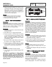
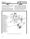
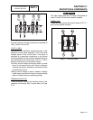
NEUTRAL
LUG
The standby generator is equipped with an
UNGROUNDED neutral. The neutral lug in the
transfer switch is isolated from the switch enclosure.
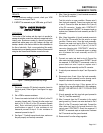
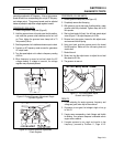
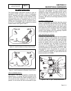
MANUAL
TRANSFER
HANDLE
The manual transfer handle is retained in the transfer
switch enclosure by means of a wing stud. Use the
handle to manually actuate the transfer mechanism
load contacts to either the UTILITY or STANDBY
source side.
Instructions on use of the manual transfer handle may
be found in Part 5, "Operational Tests and
Adjustments".
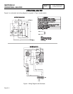
TERMINAL BLOCK
During system installation, this 5-point terminal block
must be properly interconnected with an identically
labeled terminal block in the generator control panel
assembly.
PART 3
Page 3.1-3
V-TYPE PREPACKAGED
TRANSFER SWITCHES