


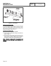
SECTION 4.4
DIAGNOSTIC TESTS
DC CONTROL
PART 4
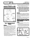
the switch terminals.
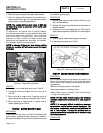
a.Set a VOM to its "R x 1" scale and zero the meter.
b.Connect the VOM test leads across the switch
terminals. With engine shut down, the meter
should read CONTINUITY.
c. Connect Wire 86 to Wire 0 for starting purposes
only. After engine starts, remove Wire 86 from
Wire 0.
d. Crank and start the engine. The meter should
read INFINITY.
5. Perform Steps 4a and 4b. If INFINITY is measured with
the engine shutdown, replace the LOP switch.
6. Set a VOM to it’s “R x 1” scale.
a.
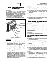
Connect one test lead to Wire 86 (disconnected from
LOP). Connect the other test lead to Pin Location 2
(Wire 86) of the J1 connector at the Circuit Board.
CONTINUITY should be measured. If CONTINUITY
is NOT measured, repair or replace Wire 86 between
the LOP switch and the J1 Connector.
b. Connect one test lead to Wire 0 ( disconnected from
LOP). Connect the other test lead to a clean frame
ground. CONTINUITY should be measured. If
CONTINUITY is NOT measured repair or replace
Wire 0 between the LOP and and the ground terminal
connection on the engine mount.
7. If the LOP switch tests good in Step 4 and oil pressure is
good in Step 3 but the unit still shuts down with a LOP
fault, check Wire 86 for a short to ground. Set a VOM to
it’s “R x 1” scale. Disconnect the J1 Connector from the
circuit board. Remove Wire 86 from the LOP switch.
Connect one test lead to Wire 86. Connect the other test
lead to a clean frame ground. INFINITY should be
measured. If CONTINUITY is measured, repair or replace
Wire 86 between the LOP switch and the J1 Connector.
RESULTS:
1. If switch tests good for Problem 9, proceed to Test 44.
2. Replace switch if it fails the test.
TEST
61-
CHECK
HIGH
OIL
TEMPERATURE
SWITCH
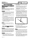
DISCUSSION:
If the temperature switch contacts have failed in a closed
position, the engine will not crank or start. If it tries to
start, it will immediately fault out on OVERTEMP. If the
unit is in an overheated condition, the switch contacts will
close at 284”F. This will normally occur from inadequate
airflow through the generator.
PROCEDURE:
1. Verify that the engine has cooled down (engine block is
cool to the touch). This will allow the contacts in the
High Oil Temperature Switch to close.
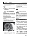
2. Check the installation and area surrounding the
generator. There should be at least three feet of clear
area around the entire unit. Make sure that there are no
obstructions preventing incoming and outgoing air.
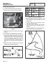
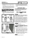
3. Disconnect Wire 85 and Wire 0 from the High Oil
Temperature Switch.
4. Set a VOM to measure resistance. Connect the test
leads across the switch terminals. The meter should
read INFINITY.
5. If the switch tested good in Step 4, and a true over-
temperature condition has not occurred, check Wire 85
for a short to ground. Remove Connector J2 (5-pin) from
the circuit board. Set the VOM to measure resistance.
Connect one test lead to Wire 85 (disconnected from High
Oil Temperature Switch). Connect the other test lead to a
clean frame ground. INFINITY should be measured.
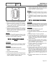
TESTING HIGH OIL TEMPERATURE SWITCH:
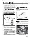
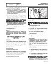
6. Remove the High Oil Temperature Switch.
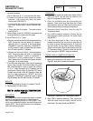
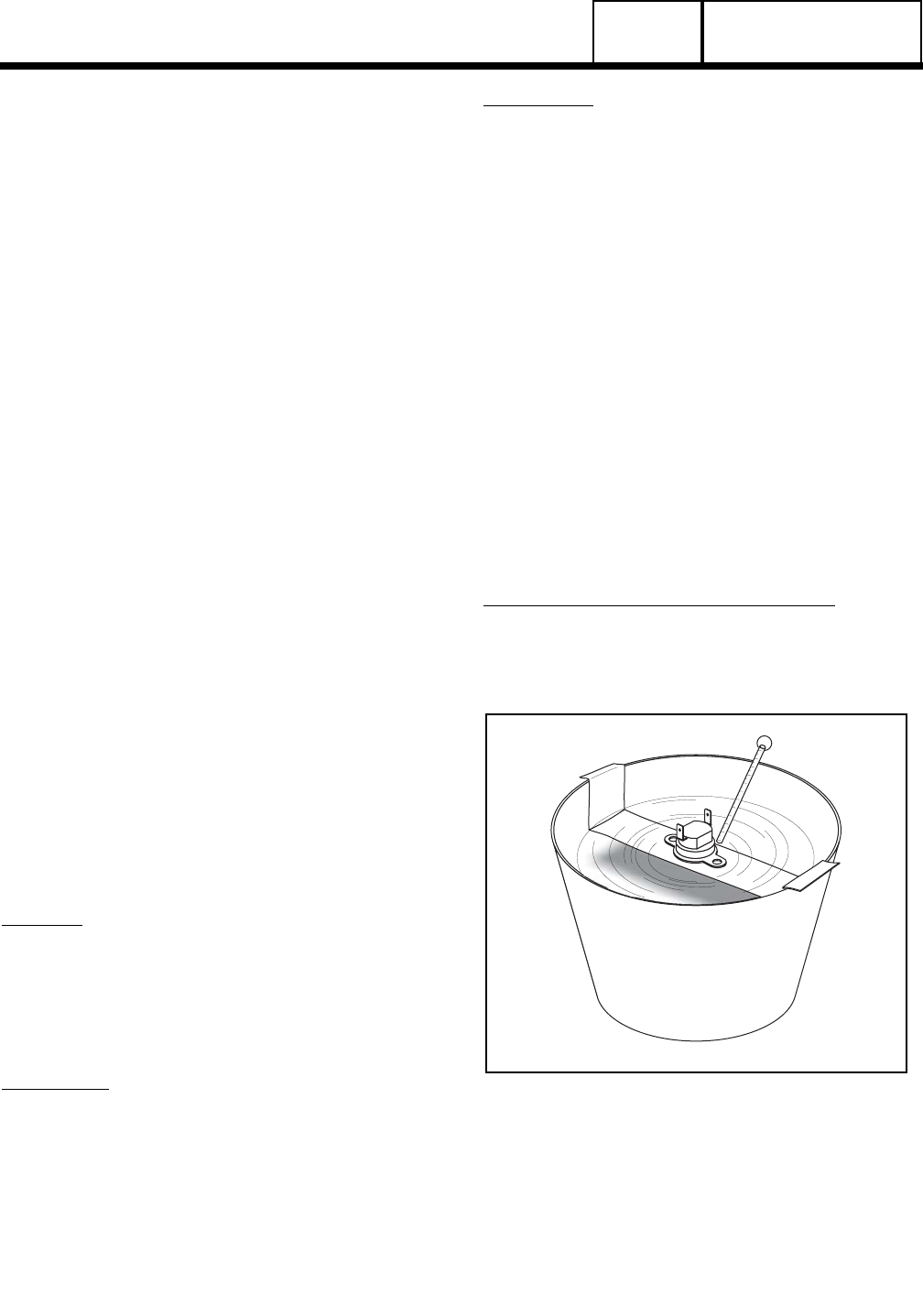
7. Immerse the sensing tip of the switch in oil as shown in
Figure 28, along with a suitable thermometer.
Figure 28. Testing the Oil Temperature Switch
8. Set a VOM to measure resistance. Then, connect the
VOM test leads across the switch terminal and the
switch body. The meter should read INFINITY.
Page 4.4-16