


SECTION 4.4
DIAGNOSTIC TESTS
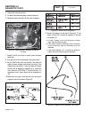
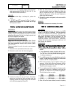
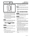
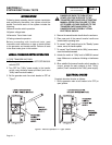
Figure 34. C2 Connector Pin Locations (Male Side)
4. Connect one test lead to Connector C2 Pin Location 1
(Wire 77). Connect the other test lead to the end of Wire
77 which was previously removed from the BCR.
CONTINUITY should be measured.
5. Connect one test lead to Connector C2 Pin Location 2
(Wire 66). Connect the other test lead to the end of Wire
66 which was previously removed from the BCR.
CONTINUITY should be measured.
RESULTS:
If CONTINUITY was NOT measured in Step 4 or Step
5, repair or replace defective wiring between
Connector C2 and the battery charge relay.
TEST
69
-
CHECK
BATTERY
CHARGER
WIRING
DISCUSSION:
The three pin connector on the battery charger
connects the charger to ground and to battery power.
PROCEDURE:
1. Set the AUTO-OFF-MANUAL switch to OFF.
2. Disconnect the three pin connector from the battery
charger.
3. Set a VOM to measure resistance.
4. Connect one meter test lead to Wire 13A at the three pin
connector. Connect the other test lead to Wire 13A at
Fuse F2. CONTINUITY should be measured.
5. Connect one meter test lead to Wire 0 at the three pin
connector. Connect the other test lead to the ground
terminal. CONTINUITY should be measured.
RESULTS:
1. If CONTINUITY was NOT measured in Step 4, repair or
replace Wire 13A between the battery charger and fuse
F2.
2. If CONTINUITY was NOT measured in Step 5, repair or
replace Wire 0 between the battery charger and frame
ground.
TEST
70
-
CHECK
ENGINE
RUN
WINDING
DISCUSSION:
The engine run winding provides an AC input through
Wire 66A to the circuit board. This input is used for
overspeed sensing. If the input is not received by the
circuit board, immediate shutdown will occur.
PROCEDURE:
1. Set the AUTO-OFF-MANUAL switch to OFF.
2. Set a VOM to measure resistance.
3. Disconnect Connector C2 from the side of the control
panel.
4. Disconnect Connector J1 from the circuit board.
5. Connect one meter test lead to Connector C2 Pin
Location 3 (Wire 66A). Connect the other test lead to
Connector J1 Pin Location 8 (Wire 66A). CONTINUITY
should be measured.
6. Connect one test lead to Connector C2 Pin Location 4
(Wire 55). Connect the other test lead to a clean frame
ground. CONTINUITY should be measured.
7. Re-connect connector C2 to the control panel, and re-
connect connector J1 to the circuit board.
8. Set a VOM to measure AC Voltage.
9. Connect the positive meter test lead to Pin Location 8,
Wire 66A of the J1 Connector on the circuit board.
Connect the negative meter test lead to the ground
terminal. Set the AUTO-OFF-MANUAL switch to
MANUAL. When the generator starts observe the
voltage output on the VOM. AC voltage should be 8-12
VAC.
10.Set VOM to measure frequency. 62- 63 HZ should be
measured.
DC CONTROL
PART 4
Page 4.4-21