


SECTION 4.4
DIAGNOSTIC TESTS
PART 4
DC CONTROL
meter to the output lugs of the generator main line
circuit breaker.
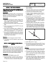
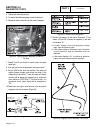
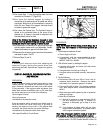
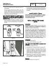
The fuel regulator is fitted with one (7 kW), or two (12 &
15 kW) adjustment screws. While watching the
frequency meter, slowly turn the adjustment screw(s)
clockwise or counterclockwise one at a time until
highest frequency is read on the meter.
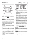
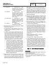
Note:
Only
limited
adjustment
is
available
between
the
set
pins
on
7
kW
fuel
regulators.
Under
no
circumstance
should
any
of
the
pins
be
removed
(see
Figures
30
&
31).
6. When the highest frequency is reached, maximum
power has been set. From this point turn the adjustment
screw(s) 1/4 turn counterclockwise. The regulator is
now set.
Figure 30
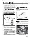
Figure 31
7. Turn utility power to the main distribution panel back on.
This can be done by switching the service main breaker
to the “ON” or closed position. Allow the generator to
shut down.
Do not make any unnecessary adjustments. Factory
settings are correct for most applications. However,
when making adjustments, be careful to avoid
overspeeding the engine.
TEST
64
-
CHECK
BATTERY
CHARGE
OUTPUT
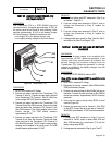
DISCUSSION:
The battery charging system is a two amp trickle
charge. It is capable of maintaining a charge on a
functional battery. It is not intended to, nor capable of
charging a completely dead battery.
The system will charge when utility source power is
available to the generator or if the generator is
running. The system consists of a transformer (TX),
battery charge relay (BCR), battery charger (BC), and
a battery charge winding. The BCR contacts allow AC
voltage to the battery charger. When the BCR is de-
energized, voltage from the TX is available to the
battery charger. When the generator starts, Wire 14
energizes the BCR. This allows battery charge
winding AC output to power the battery charger.
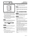
PROCEDURE:
1. Check the 5 amp fuse (F2).
2. Set the AUTO-OFF-MANUAL switch to OFF.
Note:
Utility
source
voltage
MUST
be
available
to
the
generator.
3. Set a VOM to measure DC amps.
4. Disconnect Wire 13A (purple) from the 5 amp fuse (F2).
5. Connect the positive (+) test lead to Wire 13A, and
connect the negative (-) test lead to the fuse (F2)
terminal from which Wire 13A was removed. The VOM
should measure 50 milliamps to 2.5 amps, depending
upon the state of the charge of the battery.
6. Repeat Step 5. This time set the AUTO-OFF-MANUAL
switch to MANUAL. Allow the generator to start and
then measure the current again as in Step 5.
RESULTS:
Follow the Flow Chart on Page 4.3-5.
Page 4.4-18