


SECTION 3.4
DIAGNOSTIC TESTS
V-TYPE PREPACKAGED
TRANSFER SWITCHES
GENERAL
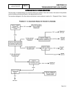
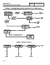
Test numbers in this section correspond to the
numbered tests in Section 3.3, "Troubleshooting Flow
Charts". When troubleshooting, first identify the
problem. Then, perform the diagnostic tests in the
sequence given in the flow charts.
TEST
21-
CHECK
VOLTAGE
AT
TERMINAL
LUGS
E1,
E2
DISCUSSION:
In automatic mode, the standby closing coil (C2) must
be energized by standby generator output if transfer
to the "Standby" source is to occur. Transfer to
"Standby" cannot occur unless that power supply is
available to the transfer switch.
DANGER: BE CAREFUL! HIGH AND
DANGEROUS VOLTAGES ARE PRESENT AT
TERMINAL LUGS E1 AND E2 WHEN THE
GENERATOR IS RUNNING. AVOID CONTACT
WITH HIGH VOLTAGE TERMINALS OR
DANGEROUS AND POSSIBLY LETHAL
ELECTRICAL SHOCK MAY RESULT. DO NOT
PERFORM THIS VOLTAGE TEST WHILE
STANDING ON WET OR DAMP GROUND,
WHILE BAREFOOT, OR WHILE HANDS OR
FEET ARE WET.
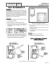
PROCEDURE:
1. If the generator engine has started automatically (due to
a utility power source outage) and is running, check the
position of the generator main circuit breaker. The
circuit breaker must be set to its "On" or "Closed"
position. When you are sure the generator main circuit
breaker is set to "On" or 'Closed", check the voltage at
transfer mechanism terminal lugs E1 and E2 with an
accurate AC voltmeter or with an accurate volt-ohm-
milliammeter (VOM). The generator line-to line voltage
should be indicated.
2. If the generator has been shut down, proceed as
follows:
a.On the generator control panel, set the AUTO-
OFF-MANUAL
switch to OFF.
b.Turn OFF all power voltage supplies to the
transfer switch. Both the utility and standby
power supplies must be positively turned off
before proceeding.
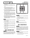
c.Check the position of the transfer mechanism
main contacts. The moveable LOAD contacts
must be connected to the stationary UTILITY
source contacts. If necessary, manually actuate
the main contacts to the "Utility" power source
side.
PART 3
Page 3.4-1
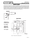
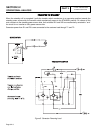
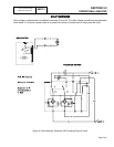
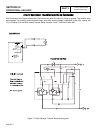
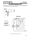
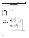
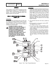
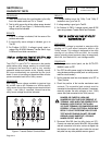
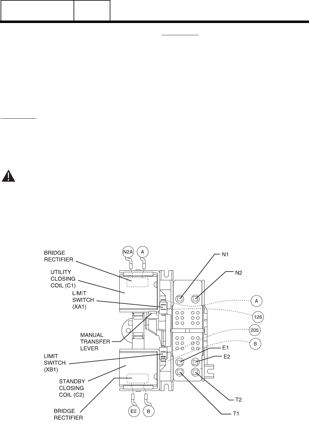
Figure 1. The “V-Type” Transfer Mechanism