


SECTION 4.4
DIAGNOSTIC TESTS
DC CONTROL
PART 4
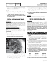
9. Heat the oil in the container. When the thermometer
reads approximately 274°-294° F. (134°-146° C.), the
VOM should indicate CONTINUITY.
RESULTS:
1. If the switch fails Step 4, or Steps 8-9, replace the
switch.
2. If INFINITY was NOT measured in Step 5, repair or
replace Wire 85 between the Circuit Board and the High
Oil Temperature Switch.
TEST
62
-
CHECK
AND
ADJUST
VALVES
DISCUSSION:
Improperly adjusted valves can cause various engine
related problems including, but not limited to, hard
starting, rough running and lack of power. The valve
adjustment procedure for both the single cylinder and
the V-twin engines is the same.
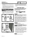
PROCEDURE (INTAKE AND EXHAUST):
Make sure that the piston is at Top Dead Center
(TDC) of it s compression stroke (both valves closed).
The valve clearance should be 0.05-0.1mm (0.002-
0.004 in) cold.
Check and adjust the valve to rocker arm clearance
as follows:
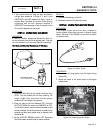
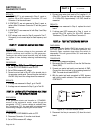
1. Remove the four (4) screws from the rocker cover.
2. Remove the rocker cover and rocker cover gasket.
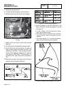
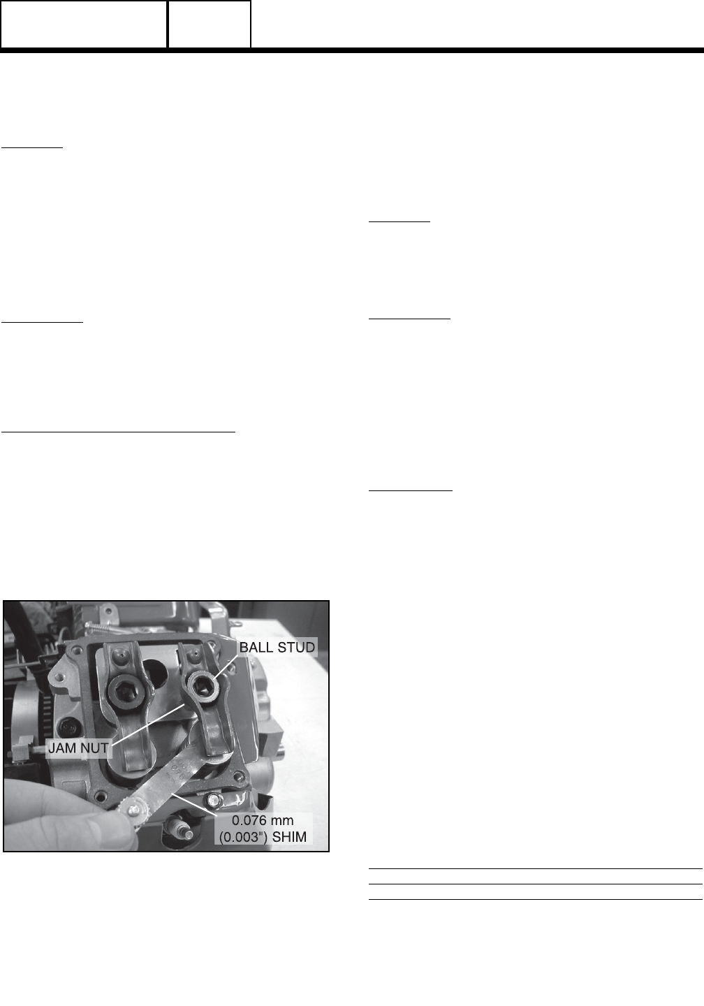
Figure 29
3. Loosen the rocker arm jam nut. Use a 10mm allen
wrench to turn the pivot ball stud and check the
clearance between the rocker arm and the valve stem
with a flat feeler gauge (see Figure 29).
4. When the valve clearance is correct, hold the pivot ball
stud with the allen wrench and tighten the rocker arm
jam nut. Torque the jam nut to 174 inch pounds. After
tightening the jam nut, recheck the valve clearance to
make sure it did not change.
5. Re-install the rocker cover gasket, rocker cover and the
four (4) screws.
RESULTS:
Adjust valve clearance as necessary, the retest.
TEST
63
-
CHECK
FUEL
REGULATOR
DISCUSSION:
The fuel regulator is rarely the cause of a HARD
START or NO START condition. The most common
causes are insufficient fuel pressure supplied to the
unit, or the adjustment screws on the fuel regulator
being out of adjustment. The fuel regulator is an ON
DEMAND type. During cranking and running,
negative pressure from the airbox or carburetor
unseats the fuel regulator diaphragms and allows fuel
flow through the regulator.
PROCEDURE:
Note:
Step
1
of
this
procedure
pertain
to
V-ttwin
engines
only.
Single
cylinder
engines
begin
at
Step
2.
1. If the adjustment screw settings are in question, reset as
follows:
a.Turn adjustment screws clockwise all the way
in, then turn out counterclockwise two and one
half full turns. This will provide a starting point
for further adjustment.
2. Turn off utility power to the main distribution panel in the
house. This can be done by switching the service main
breaker to the OFF or “Open” position.
3. Allow the generator to start. Before loading the
generator, confirm that the No Load Frequency, with the
roof open and the door off, is set to 63-63.5 Hz.
Transfer load to emergency circuits.
4. Turn on appliances. lights, pumps, etc., that are on the
emergency circuits in an attempt to fully load the
generator. Be cautious not to overload the generator.
Use the following chart as a guide:
Unit 120 Volts 240 Volts
7 kW 50.0 amps 25.0 amps
12 kW 100.0 amps 50.0 amps
15 kW 108.3 amps 54.1 amps
5. When full load has been achieved, connect a frequency
Page 4.4-17