


SECTION 3.4
DIAGNOSTIC TESTS
TEST
26
-
CHECK
23
AND
194
WIRING/CONNECTIONS
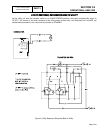
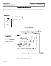
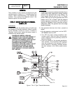
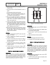
DISCUSSION:
An open circuit in the transfer switch control wiring
can prevent a transfer action from occurring. In the
auto mode, the circuit board supplies +12 VDC to
Wire 194. This DC voltage is supplied to the transfer
relay (TR) at Terminal Location A . The opposite
side of the transfer relay (TR) coil (Terminal B) is
connected to Wire 23. Positive 12VDC is present on
this also. Circuit board action will allow current to flow
through the circuit and the (TR) is energized.
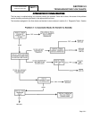
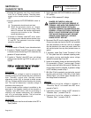
PROCEDURE/RESULTS:
1. Set VOM to DC volts
2. Place generator AUTO-OFF-MANUAL switch to the
AUTO position. Utility power should be present; the
generator should not start.
3. Connect the negative (-) test lead to a suitable frame
ground in the transfer switch.
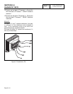
4. Connect the positive (+) test lead to Wire 194 at the
terminal strip in the transfer switch.
a.If voltage is present, proceed to Step 5.
b.If voltage is NOT present, proceed to Step 9.
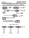
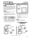
5. Connect the positive (+) test lead to Wire 23 at the
terminal strip in the transfer switch.
a.If voltage is present, proceed to Step 6.
b.If voltage is NOT present, repair wiring between
terminal strip and transfer relay (TR).
6. Connect the negative (-) test lead to the ground lug in the
generator control panel. Connect the positive (+) test
lead to Wire 23 in the generator control panel at the
interconnection terminals (ICT) or at the terminal strip.
a.If voltage is present, proceed to Step 7.
b.If voltage is NOT present, repair wiring between
transfer switch and generator control panel.
7. Connect the
positive (+)
test lead to Wire 23 located in
the J1 connector Pin Location 3, connected to the circuit
board (see Figure 3, Page 4.1-2).
a.If voltage is present, proceed to Step 8.
b.If voltage is NOT present, repair wiring between
(ICT and J1connector).
8. Turn off utility power to transfer switch, simulating a
utility failure.
a.Generator starts and transfer occurs,
discontinue tests.
b.Generator starts and transfer does NOT occur.
With the generator running and utility OFF,
ground
Wire 23 in the control panel at
interconnection terminals (ICT) or at the terminal strip.
If transfer occurs replace circuit board.
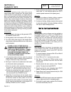
9.
Connect the negative (-) test lead to the ground lug in the
generator control panel. Connect the positive (+)
test
lead to Wire 194 in the generator control panel at the
interconnection terminals (ICT)
or at the terminal strip
.
a.If the voltage is present, repair wiring between
ICT (or terminal strip) and transfer switch
b.If voltage is NOT present, proceed to Step 10.
10.
Connect the positive (+)
test lead to Wire 194
located in
the J1 connector Pin Location 4, connected to the circuit
board (see Figure 3, Page 4.1-2).
a.If voltage is present, repair wiring between J1
connector and ICT (or terminal strip).
b.If voltage is NOT present, replace circuit board.
TEST
27-
CHECK
VOLTAGE
AT
TERMINAL
LUGS
N1,
N2
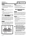
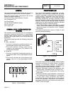
DISCUSSION:
If retransfer to the "Utility" power source side is to
occur, utility source voltage must be available to
terminal lugs N1 and N2 of the transfer mechanism.
In addition, If that source voltage is not available to
NI/N2 terminals, automatic startup and transfer to
"Standby" will occur when the generator manual-off-
auto switch is set to AUTO. This test will prove that
"Utility" voltage is available to those terminals, or is
not available. It is the first test in a series of tests that
should be accomplished when (a) retransfer back to
’Utility" does not occur, or (b) startup and transfer
occurs unnecessarily.
DANGER: PROCEED WITH CAUTION! HIGH
AND DANGEROUS VOLTAGES ARE PRESENT
AT TERMINAL LUGS N1/N2. CONTACT WITH
HIGH VOLTAGE TERMINALS WILL RESULT IN
DANGEROUS AND POSSIBLY LETHAL
ELECTRICAL SHOCK. DO NOT ATTEMPT THIS
TEST WHILE STANDING ON WET OR DAMP
GROUND, WHILE BAREFOOT, OR WHILE
HANDS OR FEET ARE WET.
V-TYPE PREPACKAGED
TRANSFER SWITCHES
PART 3
Page 3.4-5