


SECTION 6.1
MAJOR DISASSEMBLY
DISASSEMBLY
PART 6
Page 6.1-2
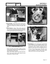
Figure 3
13.Remove Muffler: Using a 13mm socket, remove the four
muffler hold down bolts. Remove the four exhaust
manifold nuts. Remove the muffler and muffler base
panel.
14.Stator Removal: Using a 13mm socket, remove the
two nuts from the alternator mounting bracket/rubber
mounts. Lift the back end of the alternator up and place
a 2"x 4" piece of wood under the engine adapter.
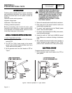
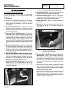
Figure 4. Engine Adapter Supported by
2”x4” Piece of Wood
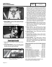
Using a 1/4" socket, remove Wire 0 and Wire 4 from the
brush assembly. Remove the two brush assembly hold
down bolts. Remove the brushes.
Using a 13mm socket, remove the four stator hold down
bolts. Using a small rubber mallet remove the rear
bearing carrier. Remove the stator.
Figure 5. Rear Bearing Carrier Removed
Figure 6. Removing the Stator
15.Rotor Removal: Cut 2.5 inches from the rotor bolt. Slot
the end of the bolt to suit a flat blade screwdriver. Slide
the rotor bolt back through the rotor and use a
screwdriver to screw it into the crankshaft. Use a 3"
M12x1.75 bolt to screw into rotor. Apply torque to the
3" M12x1.75 bolt until taper breaks. If necessary, when
torque is applied to 3" M12x1.75 bolt, use a rubber
mallet on the end of the rotor shaft to break taper.