


SECTION 4.4
DIAGNOSTIC TESTS
PART 4
J1-4, Wire 194 If CONTINUITY was
measured, go to Step 4.
Average nominal resistance
reading: 110-120 ohms.
J1-5, Wire 56 If CONTINUITY was
measured, go to Step 5.
Average nominal resistance
reading V-twin (SCR): 150-
160 ohms, Single Cylinder
(SC): 4 ohms.
J1-10, Wire 15A If CONTINUITY was
measured, repair or replace
shorted to ground Wire 15A
between Connector J1 and
switch SW1.
J1-7, Wire 14 If CONTINUITY was
measured, go to Step 6.
4. Disconnect Wire 194 from the terminal strip. Repeat
Step 3 at Pin Location J1-4.
a.If CONTINUITY was measured, Wire 194 is
shorted to ground between Connector J1 and
terminal strip.
b.If INFINITY was measured, disconnect Wire 194
from the transfer switch terminal strip. Connect
one meter test lead to the end of Wire 194
which was removed from the transfer switch
terminal strip. Connect the other meter test lead
to the ground terminal. If CONTINUITY was
measured, Wire 194 is shorted to ground
between the generator and the transfer switch.
1) If INFINITY was measured, disconnect Wire
194 from the transfer relay (TR). Connect
one meter test lead to the transfer relay
terminal from which Wire 194 was previously
removed. Connect the other test lead to Wire
23 at the transfer switch terminal strip. If
CONTINUITY ZERO RESISTANCE was
measured, replace the transfer relay. Normal
coil resistance is approximately 113 ohms.
2) If coil resistance of 113 ohms was
measured, the short is in Wire 194 between
the transfer relay and the terminal strip.
Repair or replace Wire 194.
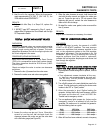
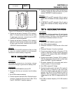
5. Disconnect Wire 56 From the starter contactor relay
(SCR on V-twin) or the starter contactor (SC on single
cylinder). Connect one meter test lead to the SCR or SC
terminal from which Wire 56 was removed. Connect the
other meter test lead to the ground terminal. If
CONTINUITY or zero resistance was measured,
replace the SCR or SC. Coil resistance for the SCR is
155 ohms. Coil resistance for the SC is 4 ohms. If coil
resistance was measured, Wire 56 is shorted to ground
between Connector J1 and the SCR or SC. Repair or
replace the shorted wire.
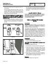
6. Disconnect and isolate each Wire 14 from the 4-tab
insulated terminal block. Repeat Step 3 for Pin Location
J1-7. If CONTINUITY was measured, repair or replace
Wire 14 between Connector J1 and the 4-tab terminal
block. If INFINITY was measured, proceed as follows:
a.Disconnect Wire 14 from the following: fuel
solenoid (FS), battery charge relay (BCR) and
hourmeter (HM) if equipped.
b.Connect the negative (-) meter test lead to the
ground terminal. Connect the positive (+) meter
test lead to each of the listed components at the
terminal from which Wire 14 was removed. If
CONTINUITY or zero resistance was measured,
the component has shorted to ground. Replace
the component. The average nominal resistance
value that should be measured for each
component is:
Battery Charge Relay (BCR) - 112 ohms
Fuel Solenoid (FS) - 31 ohms
Hourmeter (HM) - 2 Mega ohms to infinity
c. If each component tests good, there is no short
to ground. The fault exists in one of the Wire 14
wires. Connect one meter test lead to the ground
terminal. Connect the other meter test lead to
each Wire 14 individually (on the end removed
from the BCR, FS or HM). The Wire 14 which
measures CONTINUITY is shorted to ground.
Repair or replace the affected wire between the
component and the 4-tab terminal block.
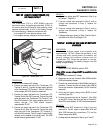
TEST
77
-
TEST
EXERCISE
FUNCTION
DISCUSSION:
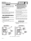
The following parameters must be met in order for the
weekly exercise to occur:
❏AUTO-OFF-MANUAL switch (SW1) set to AUTO.
❏Circuit board DIP Switch 2 (REMOTE NOT AUTO)
set to OFF.
DC CONTROL
Page 4-4.24