


SECTION 2.4
DIAGNOSTIC TESTS
PART 2
AC GENERATORS
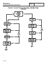
TEST WINDINGS FOR A SHORT TO GROUND:
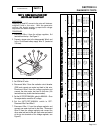
13. Make sure all leads are isolated from each other and
are not touching the frame.
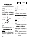
14. Set a VOM to its "R x 10,000" or "R x 1K" scale and
zero the meter
15.Connect one test lead to a clean frame ground.
Connect the other test lead to stator lead Wire 11.
a. The meter should read INFINITY
b. Any reading other than INFINITY indicates a
"short-to-ground" condition.
16. Repeat Step 15 using stator lead Wire 33.
17. Repeat Step 15 using Pin 1.
18. Repeat Step 15 using Pin 3
19. Repeat Step 15 using Pin 5
20. Repeat Step 15 using Pin 7
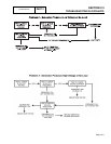
TEST FOR A SHORT CIRCUIT BETWEEN WINDINGS:
21. Set a VOM to its "R x 10,000" or "R x 1K" scale and
zero the meter.
22. Connect one test lead to stator lead Wire 11. Connect
the other test lead to stator lead Wire 33.
a. The meter should read INFINITY.
b. Any reading other than INFINITY indicates a short
circuit between windngs.
23. Repeat Step 22 using stator lead Wire 11; Pin 1
24. Repeat Step 22 using stator lead Wire 11; Pin 3
25 Repeat Step 22 using stator lead Wire 11; Pin 7
26. Repeat Step 22 using stator lead Wire 33; Pin 1
27. Repeat Step 22 using stator lead Wire 33; Pin 3
28. Repeat Step 22 using stator lead Wire 33; Pin 7
29. Repeat Step 22 using Pin 1; Pin 3
30. Repeat Step 22 using Pin 1; Pin 7
31. Repeat Step 22 using Pin 3; Pin 7
TEST CONTROL PANEL WIRES FOR CONTINUITY:
32.Set a VOM to its "Rx1" scale.
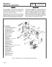
33.Disconnect the C2 connector from the control panel. (C2
is the closest to the back panel). Refer to Figure 6 for
pin locations.
33.Connect one meter test lead to Pin 5 of the C2
connector, connect the other test lead to Wire 22 at the
voltage regulator. CONTINUITY should be measured.
34.Connect one meter test lead to Pin 6 of the C2
connector, connect the other test lead to Wire 11 at the
voltage regulator. CONTINUITY should be measured.
35.Connect one meter test lead to Pin 7 of the C2
connector, connect the other test lead to Wire 6 at the
voltage regulator. CONTINUITY should be measured.
36.Connect one meter test lead to Pin 8 of the C2
connector, connect the other test lead to Wire 2 at CB2
(DPE circuit breaker). CONTINUITY should be
measured.
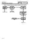
RESULTS:
1. Stator winding resistance values is a test of winding
continuity and resistance. If a very high resistance or
INFINITY is indicated, the winding is open or partially
open.
2. Testing for a "grounded" condition: Any upscale
movement of the meter needle or dial indicates the
winding is grounded.
3. Testing for a "shorted" condition: Any upscale
movement of the VOM needle or dial indicates the
winding is shorted.
4. If the stator tests good and wire continuity tests good ,
perform “Insulation Resistance Test” on page 1.4-4.
5. If any test of wire continuity failed in control panel failed,
repair or replace the wire, terminal or pin connectors for
that associated wire as needed.
NOTE: Read section 1.4, "Testing, Cleaning and
Drying" carefully. If the winding tests good, perform an
insulation resistance test. If the winding fails the
insulation resistance test, clean and dry the stator as
outlined in Section 1.4. Then, repeat the insulation
resistance test. If the winding fails the second
resistance test (after cleaning and drying), replace
the stator assembly.
TEST
8
-
RESISTANCE
CHECK
OF
ROTOR
CIRCUIT
DISCUSSION:
To verify the zero current draw reading and measure the
rotor circuit.
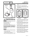
PROCEDURE:
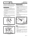
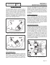
1. Disconnect Wire 4 from the voltage regulator. It is
located 3rd terminal from the top of the volt regulator.
2. Set VOM to the "Rx1" scale.
3. Connect one test lead to Wire 4. Connect the other test
lead to a clean frame ground. Note the resistance
reading. Compare to specifications on Page 2.
Page 2.4-6