


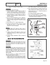

SECTION 4.4
DIAGNOSTIC TESTS
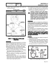
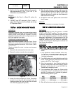
1. Remove both spark plugs.
2. Insert a compression gauge into either cylinder.
3. Crank the engine until there is no further increase in
pressure.
4. Record the highest reading obtained.
5. Repeat the procedure for the remaining cylinder and
record the highest reading.
RESULTS:
The difference in pressure between the two cylinders
should not exceed 25 percent. If the difference is
greater than 25 percent, loss of compression in the
lowest reading cylinder is indicated.
Example
1:
If the pressure reading of cylinder #1 is 65
psi and of cylinder #2, 60 psi, the difference is 5 psi.
Divide "5" by the highest reading (65) to obtain the
percentage of 7.6 percent.
Example
2:
No. 1 cylinder reads 75 psi; No. 2 cylinder
reads 55 psi. The difference is 20 psi. Divide "20" by
"75" to obtain "26.7" percent. Loss of compression in
No. 2 cylinder is indicated.
If compression is poor, look for one or more of the
following:
Loose cylinder head bolts.
Failed cylinder head gasket.
Burned valves or valve seats.
Insufficient valve clearance.
Warped cylinder head.
Warped valve stem.
Worn or broken piston ring(s).
Worn or damaged cylinder bore.
Broken connecting rod.
Worn valve seats or valves.
TEST
58
-
CHECK
SHUTDOWN
WIRE
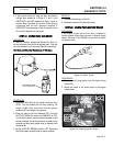
DISCUSSION:
Circuit board action during shutdown will ground Wire
18. Wire 18 is connected to the Ignition Magneto(s).
The grounded magneto will not be able to produce
spark.
PROCEDURE:
1. On v-twin generators, remove Wire 18 from the stud
located above the oil cooler. On single cylinder
generators, disconnect Wire 18 at the bullet connector.
2. Perform Test 55.
3. If spark now occurs with Wire 18 removed, check for a
short to ground. Set the AUTO-OFF-MANUAL switch to
OFF. Remove the 17 pin connector J1 from the circuit
board.
4. Set a VOM to measure resistance. Connect one test
lead to Wire 18 from the control panel. Connect the
other test lead to a clean frame ground. INFINITY
should be measured.
5. Reconnect the J1 connector to the circuit board.
6. Set a VOM to measure resistance. Connect one test
lead to Wire 18 from the control panel. Connect the
other test lead to a clean frame ground. Set the AUTO-
OFF-MANUAL switch to MANUAL. During cranking the
meter should read INFINITY.
RESULTS:
1. If INFINITY was NOT measured in Step 4, repair or
replace shorted ground Wire 18 between the J1
connector from the circuit board to the stud or bullet
connector.
2. If INFINITY was NOT measured in Step 6 during
cranking, replace the circuit board and retest for spark.
3. If ignition spark still has not occurred, proceed to
Test 59.
TEST
59
-
CHECK
AND
ADJUST
IGNITION
MAGNETOS
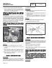
DISCUSSION:
In Test 55, a spark tester was used to check for
engine ignition. If sparking or weak spark occurred,
one possible cause might be the ignition magneto(s).
This test consists of adjusting the air gap between the
ignition magneto(s) and the flywheel. The flywheel
and flywheel key will also be checked during this test.
PROCEDURE:
Note:
The
air
gap
between
the
ignition
magneto
and
the
flywheel
on
single
cylinder
engines
is
non-
adjustable.
Proceed
directly
to
Steps
15,16
and
17
for
single
cylinder
engines.
For
V-ttwin
engines,
proceed
as
follows.
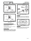
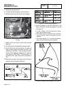
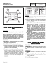
1. See Figure 23. Rotate the flywheel until the magnet is
under the module (armature) laminations.
2. Place a 0.008-0.012 inch (0.20-0.30mm) thickness
gauge between the flywheel magnet and the module
laminations.
3. Loosen the mounting screws and let the magnet pull the
magneto down against the thickness gauge.
DC CONTROL
PART 4
Page 4.4-13