


SECTION 4.4
DIAGNOSTIC TESTS
RESULTS:
1. If CONTINUITY is not measured in Step 5, repair or
replace Wire 66A between Connector C2 and
Connector J1 at the circuit board.
2. If CONTINUITY was not measured in Step 6, repair or
replace Wire 55 between Connector C2 and the ground
terminal.
3. If CONTINUITY was measured in both Step 5 and Step
6, go to Test 7.
4. If AC voltage is not correct in Step 9, proceed to Test 7.
If frequency is not correct adjust no load frequency and
re-test.
TEST
71
-
CHECK
N1
AND
N2
VOLTAGE
DISCUSSION:
Loss of utility source voltage to the generator will
initiate a startup and transfer by the generator.
Testing at the control panel terminal strip will divide
the system in two, thereby reducing troubleshooting
time.
PROCEDURE:
Note:
Verify
that
Utility
Source
Voltage
is
present.
1. Set the AUTO-OFF-MANUAL switch to OFF.
2. Set a VOM to measure AC voltage.
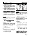
3. Connect one test lead to Wire N1 at the terminal strip in
the generator control panel. Connect the other test lead to
Wire N2. Utility line-to-line voltage should be measured.
RESULTS:
1. If voltage was measured in Step 3, go to Test 65.
2. If voltage was not measured in Step 3, go to Test 28.
TEST
72
-
CHECK
UTILITY
SENSING
VOLTAGE
AT
THE
CIRCUIT
BOARD
DISCUSSION:
If the generator starts and transfer to STANDBY
occurs in the automatic mode, even though an
acceptable UTILITY source voltage is available from
the Transformer (TX), the next step is to determine if
that sensing voltage is reaching the circuit board.
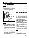
PROCEDURE:
1. Set the AUTO-OFF-MANUAL switch to OFF.
2. Disconnect Connector J1 from the circuit board.
3. Set a VOM to measure AC voltage.
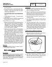
4. Connect one meter test lead to Pin Location J1-14
(Wire 225). Connect the other test lead to Pin Location
J1-15 (Wire 224). Approximate
ly 14-16 VAC should be
measured.
RESULTS:
1. If voltage was measured in Step 4, replace the circuit
board.
2. If voltage was NOT measured in Step 4, repair or
replace Wire 224 and/or No. Wire 225 between
Transformer (TX) and Circuit Board Connector J1.
TEST
73
-
TEST
SET
EXERCISE
SWITCH
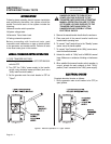
DISCUSSION:
If the Set Exercise Switch (SW2) fails closed, the unit
will start when in AUTO. In normal operation the
Normally Open contacts close when the switch is
depressed. This will ground Wire 351 and reset the
exercise time.
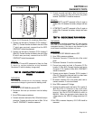
PROCEDURE:
1. Set a VOM to measure resistance.
2. Disconnect Wire 351 and Wire 0 from the Set Exercise
Switch (SW2).
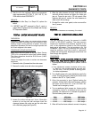
3. Connect one meter test lead to one terminal of SW2.
Connect the other test lead to the remaining terminal of
SW2. The meter should read INFINITY.
4. With the meter test leads connected to SW2, depress
and hold the switch activated. The meter should read
CONTINUITY.
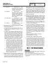
Figure 35. The Set Exercise Switch
5. Disconnect the five pin connector (J2) from the circuit
board.
PART 4
DC CONTROL
Page 4.4-22