


SECTION 4.1
DESCRIPTION AND COMPONENTS
DC CONTROL
PART 4
Page 4.1-2
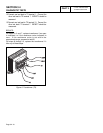
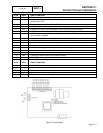
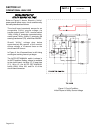
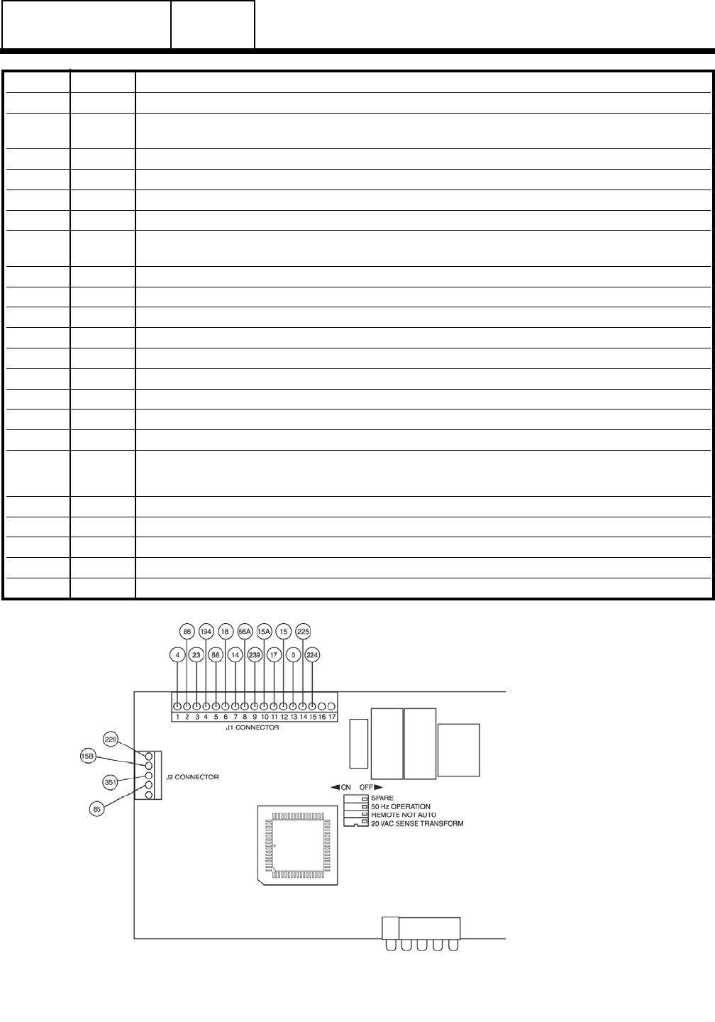
J1 PIN WIRE CIRCUIT FUNCTION
1 4 Field boost current to rotor (about 9-10 volts DC).
2 86 Low oil pressure shutdown. Automatic shutdown occurs when Wire 85 is grounded by loss of oil
pressure to the LOP.
3 23 Switched to ground for Transfer Relay (TR) operation.
4 194 12 VDC output from the circuit board for transfer relay, present in AUTO or MANUAL operation.
5 56 Energized (12 volts DC) by circuit board’s crank relay (K1) to crank the engine.
6 18 Engine shutdown. Circuit is grounded by circuit board action to ground the engine
7 14 12 VDC output for engine run condition. Used for fuel solenoid (FS), battery charge relay (BCR),
and hourmeter if equipped.
8 66A AC input to the board for crank terminate and overspeed protection.
9 239 B+ input when SW1 is in the MANUAL position.
10 15A B+ input into the board for source voltage when SW1 is in the AUTO or MANUAL position.
11 17 B+ output to SW1 for manual start operation.
12 15 12VDC source voltage for the circuit board. Also runs timer for exerciser.
13 0 Common ground.
14 225 Transformer reduced "Utility" source sensing voltage.
15 224 Transformer reduced "Utility" source sensing voltage.
16 NOT USED
17 NOT USED
J2 PIN WIRE CIRCUIT FUNCTION
1 NOT USED
2 85 High temperature oil engine safety.
3 351 Input set exercise. Signal to ground to set.
4 15B Output for remote alarm relay, optional.
5 229 Output for remote alarm relay, optional.
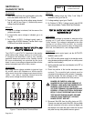
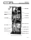
Figure 3. Circuit Board