


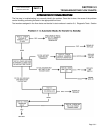
SECTION 3.4
DIAGNOSTIC TESTS
6. Set the generator main line circuit breaker to its "On" or
"Closed" position.
7. Set the generator AUTO-OFF-MANUAL switch to
AUTO.
a.The generator should crank and start.
b.About 15 seconds after engine startup, the
transfer relay should energize and transfer to
the ’Standby" source should occur.
8. When you are certain that transfer to "Standby" has
occurred, turn ON the utility power supply to the transfer
switch. After a 15 seconds, retransfer back to the
"Utility" source should occur.
9. Locate on the utility closing coil the terminal that Wire A
is connected to (see Figure 1, Page 3.4-1). Connect the
other meter test lead to this terminal. Generator line to
line voltage should be indicated. If generator voltage
is NOT indicated, proceed to Step 10.
10.With Wire N2A still connected to one test probe, connect
the other meter test lead to Wire 126 on Limit Switch
XA1 (see Figure 1, Page 3.4-1). Generator line to line
voltage should be measured.
RESULTS:
1. In Step 7, if the generator does NOT crank or start, refer
to Part 4, "DC Control".
2. In Step 7, if transfer to the "Standby" source does NOT
occur, go to Problem 1.
3. In Step 9, if normal utility source line-to-line voltage is
indicated but retransfer back to "Utility" does NOT
occur, go to Test 24.
4. If normal utility source line-to-line voltage is NOT
indicated in Step 9, but is indicated in Step 10,
proceed to Test 31.
5. If normal utility source line-to-line voltage is NOT
indicated in Step 8, and is NOT indicated in Step 9,
proceed to Test 32.
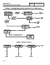
TEST
30
-
CHECK
FUSES
F1
AND
F2
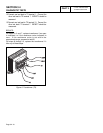
DISCUSSION:
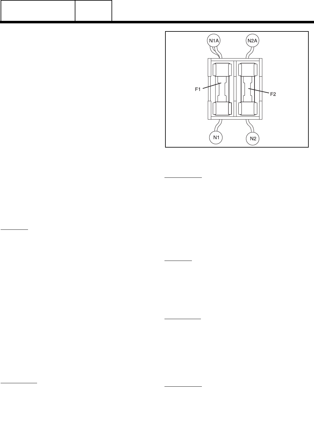
Fuses F1 and F2 are connected in series with the
Utility 1 and Utility 2 circuits, respectively. A blown
fuse will open the applicable circuit and will result in
(a) generator startup and transfer to "Standby", or (b)
failure to retransfer back to the UTILITY source.
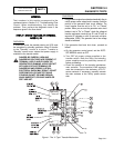
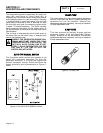
Figure 5. Fuse Holder and Fuses
PROCEDURE:
1. On the generator panel, set the AUTO-OFF-MANUAL
switch to OFF.
2. Turn off the utility power supply to the transfer switch,
using whatever means provided.
3. Remove fuses F1 and F2 from the fuse holder (see
Figure 5).
4. Inspect and test fuses for blown condition.
RESULTS:
1. Replace blown fuse(s) and proceed to Test 34.
2. For Problem 7 (DC Control section), go to Test 27.
TEST
31
-
TEST
LIMIT
SWITCH
XA1
DISCUSSION:
When the transfer switch main contacts are actuated
to their "Utility" position, limit switch XA1 should be
mechanically actuated to its open position. On
transfer to the "Standby" position, the limit switch
should actuate to its closed position. If the switch
does not actuate to its closed position, retransfer back
to "Utility" will not occur.
PROCEDURE:
1. With the standby generator shut down, set its AUTO-
OFF-MANUAL switch to OFF.
2. Turn OFF the utility power supply to the transfer switch,
using whatever means provided.
V-TYPE PREPACKAGED
TRANSFER SWITCHES
PART 3
Page 3.4-7