


SECTION 3.2
OPERATIONAL ANALYSIS
V-TYPE PREPACKAGED
TRANSFER SWITCHES
PART 3
Page 3.2-2
UTILITY
SOURCE
VOLTAGE
AVAILABLE
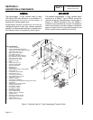
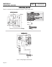
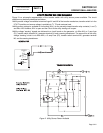
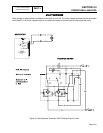
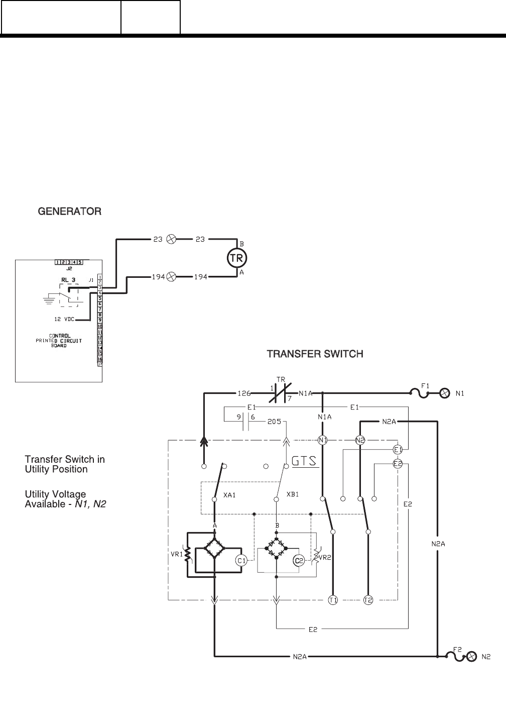
Figure 2 is a schematic representation of the transfer switch with utility source power available. The circuit
condition may be briefly described as follows:
❏Utility source voltage is available to terminal lugs N1 and N2 of the transfer mechanism, transfer switch is in the
UTILITY position and source voltage is available to T1, T2 and customer load.
❏Utility source voltage is available to limit switch (XA1) via the normally-closed transfer relay contacts (1 and 7)
and Wire 126. However, XA1 is open and the Circuit to the utility closing coil is open.
❏Utility voltage "sensing" signals are delivered to a circuit board on the generator, via Wire N1A, a 5 amp fuse
(F1), transfer switch terminal N1, generator terminal N1 and a sensing transformer. The second line of the utility
voltage "sensing" circuit is via Wire N2A, a 5 amp Fuse (F2), transfer switch terminal N2, generator terminal
N2, and the sensing transformer.
Figure 2. Utility Source Power Available