


SECTION 2.4
DIAGNOSTIC TESTS
PART 2
AC GENERATORS
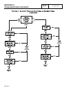
TEST
2-
CHECK
AC
OUTPUT
VOLTAGE
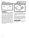
DISCUSSION:
A volt-ohm-milliammeter (VOM) may be used to
check the generator output voltage. Output voltage
may be checked at the unit’s main circuit breaker
terminals. Refer to the unit’s DATA PLATE for rated
line-to-line and line-to-neutral voltages.
DANGER: USE EXTREME CAUTION DURING
THIS TEST. THE GENERATOR WILL BE
RUNNING. HIGH AND DANGEROUS
VOLTAGES WILL BE PRESENT AT THE TEST
TERMINALS. CONNECT METER TEST CLAMPS
TO THE HIGH VOLTAGE TERMINALS WHILE
THE GENERATOR IS SHUT DOWN. STAY
CLEAR OF POWER TERMINALS DURING THE
TEST. MAKE SURE METER CLAMPS ARE
SECURELY ATTACHED AND WILL NOT SHAKE
LOOSE.
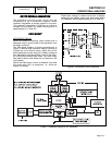
PROCEDURE:
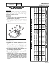
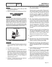
1. With the engine shut down, connect the AC voltmeter
test leads across the Wires 11 and 44 terminals of the
generator main circuit breaker (see Figure 1). These
connections will permit line-to-line voltages to be read.
2. Set the generator main circuit breaker to its OFF or
"Open" position. This test will be conducted with the
generator running at no-load.
3. Start the generator, let it stabilize and warm up for a
minute or two.
4. Take the meter reading. On unit's having a rated line-to-
line voltage of 240 volts, the no-load voltage should be
about 242-252 volts AC.
5. Shut the engine down and remove the meter test leads.
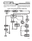
RESULTS:
1. If zero volts or residual voltage is indicated, go on to
Test 3.
2. If the voltage reading is higher than residual, but is lower
than the stated limits, go to Test 11.
3. If a high voltage is indicated, go on to Test 11.
NOTE:
"Residual"
voltage
may
be
defined
as
the
voltage
that
is
produced
by
rotor
residual
magnetism
alone.
The
amount
of
voltage
induced
into
the
stator
AC
power
windings
by
residual
voltage
alone
will
be
approximately
2
to
16
volts
AC,
depending
on
the
characteristics
of
the
specific
generator.
If
a
unit
is
supplying
residual
voltage
only,
either
excitation
current
is
not
reaching
the
rotor
or
the
rotor
windings
are
open
and
the
excitation
current
cannot
pass.
On
current
units
with
air-ccooled
engine,
"field
boost"
current
flow
is
available
to
the
rotor
only
during
engine
cranking.
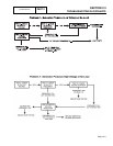
TEST
3-
TEST
EXCITATION
CIRCUIT
BREAKER
DISCUSSION:
Unregulated excitation current is delivered to the
voltage regulator from the stator excitation (DPE)
winding, via Wire 2, an excitation circuit breaker
(CB2), Wire 162, and Wire 6. If the excitation circuit
breaker has failed open, excitation current will not be
available to the voltage regulator or to the rotor.
Stator AC power winding output will then be reduced
to a voltage that is the product of residual magnetism
alone.
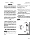
PROCEDURE:
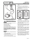
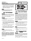
1. With the generator shut down for at least two minutes,
locate the excitation circuit breaker in the generator
panel. Disconnect wires from the breaker, to prevent
interaction.
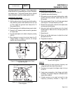
2. Set a volt-ohm-milliammeter (VOM) to its "R x 1'scale
and zero the meter.
3. Connect the VOM test probes across the circuit breaker
terminals. The meter should read CONTINUITY.
RESULTS:
1. Replace circuit breaker if defective (meter reads
“OPEN”). Then proceed to Test 4.
2. If circuit breaker is good, go on to Test 4.
Figure 2. Excitation Circuit Breaker
Page 2.4-2