


SECTION 3.4
DIAGNOSTIC TESTS
PART 3
V-TYPE PREPACKAGED
TRANSFER SWITCHES
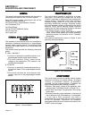
3. To prevent interaction, disconnect Wire 126 and Wire
"A" from the limit switch terminals.
4. Set a VOM to its "R x 1 " scale and zero the meter.
5. Connect the VOM test leads across the two limit switch
terminals from which Wires A and 126 were removed.
6. Manually actuate the main contacts to their "Standby"
position. The VOM should indicate CONTINUITY.
7. Manually actuate the main contacts to their "Utility"
position. The VOM should read INFINITY.
RESULTS:
Replace limit switch XA1 if it checks bad.
NOTE:
Problems
with
transfer
switch
operation
can
also
be
caused
by
(a)
defective
wiring
between
the
generator
and
transfer
switch,
or
(b)
a
defective
component
in
the
generator
circuit
board.
See
Part
4,
"DC
Control".
TEST
32
-
CONTINUITY
TEST
OF
WIRING
(C1)
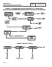
DISCUSSION:
This test will ensure that all control wiring has continuity.
1. Set the AUTO-OFF-MANUAL switch to the OFF
position.
2. Turn the generator main circuit breaker to the off position.
3. Turn off the utility power supply to the transfer switch
using whatever means provided. (Such as utility source
main line circuit breaker).
4. Set your VOM to the "R x 1" scale.
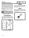
5. Disconnect Wire N2A from the Utility Coil C1 and
connect one test lead to it. Connect the other test lead
to terminal lug N2 of the transfer switch. CONTINUITY
should be read. Reconnect Wire N2A.
6. Disconnect Wire 126 from transfer relay (TR) and
connect one test lead to it. Connect the other test lead
to limit switch XA1 bottom terminal Wire 126.
CONTINUITY should be read. Reconnect Wire 126.
7. Disconnect Wire N1A from transfer relay (TR) terminal
and connect one test lead to it. Connect the other test
lead to F1 top fuse terminal Wire N1A. CONTINUITY
should be read. Reconnect Wire N1A.
RESULTS:
Repair any defective wiring that does not read
CONTINUITY. If wiring tests good, proceed to Test 23.
TEST
33
-
CONTINUITY
TEST
OF
WIRING
(C2)
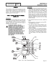
DISCUSSION:
This test will ensure that all control wiring has continuity.
1. See Test 32, Step 1
2. See Test 32, Step 2
3. See Test 32, Step 3
4. See Test 32, Step 4
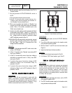
5. Disconnect Wire E2 from the standby coil (C2) and
connect one test lead to it. Connect the other test lead
to Terminal Lug E2 of the transfer switch. CONTINUITY
should be read. Reconnect Wire E2.
6. Disconnect Wire 205 from transfer relay (TR) Terminal 6
and connect one test lead to it. Connect the other test
lead to limit switch XB1 top terminal Wire 205.
CONTINUITY should be read. Reconnect Wire 205.
7. Disconnect Wire E1 from Transfer Relay (TR) Terminal
9 and connect one test lead to it. Connect the other test
lead to terminal lug E1 of the transfer switch.
CONTINUITY should be read. Reconnect Wire E1.
RESULTS:
Repair any defective wiring that does not read
CONTINUITY. If wiring tests good, proceed to Test 23.
TEST
34
-
CHECK
N1
AND
N2
WIRING
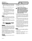
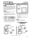
DISCUSSION:
A shorted Wire N1 or N2 to ground can cause fuse F1
or F2 to blow.
PROCEDURE:
1. On the generator panel, set the AUTO-OFF-MANUAL
switch to OFF.
2. Turn off the utility power supply to the transfer switch,
using whatever means are provided.
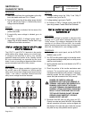
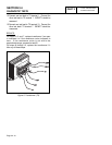
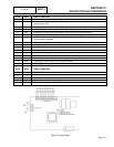
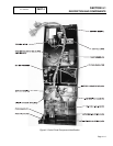
3. Remove fuses F1 and F2 from the fuse holder (see Figure 5).
4. Remove the generator control panel cover. Disconnect
wire N1 and wire N2 from the interconnection terminal in
the control panel, or the terminal strip.
5. Set your VOM to the 'R x 1" scale. Connect the positive
meter test lead to wire N1.
Page 3.4-8