


SECTION 3.4
DIAGNOSTIC TESTS
PART 3
V-TYPE PREPACKAGED
TRANSFER SWITCHES
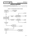
d.Actuate the generator main line circuit breaker
to its "On" or "Closed" position. The utility power
supply to the transfer switch must be turned
OFF.
e.Set the generator AUTO-OFF-MANUAL switch to
AUTO.
(1) The generator should crank and start.
(2) When the generator starts, an "engine
warm-up timer" should start timing. After
about 15 seconds, the transfer relay should
energize and transfer to the "Standby"
source should occur.
f. If transfer to "Standby" does NOT occur, check
the voltage across transfer switch terminal lugs
E1 and E2. The generator line-to-line voltage
should be indicated.
RESULTS:
1. If normal transfer to "Standby" occurs, discontinue tests.
2. If transfer to "Standby" does NOT occur and no voltage
is indicated across terminal lugs E1/E2, determine why
generator AC output has failed.
3. If transfer to "Standby" does NOT occur and voltage
reading across terminal lugs E1/E2 is good, go on to
Test 22.
TEST
22
-
CHECK
VOLTAGE
AT
STANDBY
CLOSING
COIL
C2
DISCUSSION:
Standby source voltage is used to energize the
standby closing coil and actuate the main contacts to
their "Standby" source side. Standby source
alternating current (AC) is changed to direct current
(DC) by a bridge rectifier before reaching the closing
coil. This test will determine if standby voltage is
available to the closing coil.
If normal standby source voltage is available to the
terminals of the standby closing coil but transfer to
"Standby" does NOT occur, look for (a) binding or
sticking in the transfer mechanism, (b) a defective
coil, or (c) a bad bridge rectifier. The coil and the
bridge rectifier must be replaced as a unit.
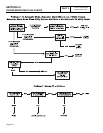
PROCEDURE:
1. Set the generator main line circuit breaker to the OFF or
“Open” position.
2. Set the generators AUTO-OFF-MANUAL switch to the
OFF position.
3. Set your VOM to measure AC voltage.
DANGER: BE CAREFUL! HIGH AND
DANGEROUS VOLTAGES ARE PRESENT AT
TERMINAL LUGS WHEN THE GENERATOR IS
RUNNING. AVOID CONTACT WITH HIGH
VOLTAGE TERMINALS OR DANGEROUS AND
POSSIBLY LETHAL ELECTRICAL SHOCK MAY
RESULT. DO NOT PERFORM THIS VOLTAGE
TEST WHILE STANDING ON WET OR DAMP
GROUND, WHILE BAREFOOT, OR WHILE
HANDS OR FEET ARE WET.
4. Disconnect Wire E2 from the standby closing coil (C2).
Connect one meter test Lead to Wire E2. Use a suitable
and safe connection to this wire, such as an alligator
clip that attaches to the meter test probe. Isolate this
wire and test probe from any other potential source or
ground.
5. If necessary, repeat Step 2 under "Procedure" of Test
21. The system must be in automatic operating mode,
with engine running, and standby source voltage
available to terminal lugs E1 and E2.
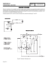
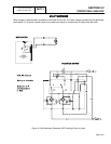
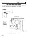
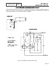
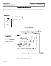
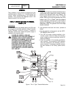
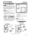
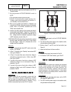
6. Locate on the standby closing coil the terminal that Wire
B is connected to. (Figure 1, previous page). Connect
the other meter test lead to this terminal. Generator line
to line voltage should be indicated. If generator voltage
is NOT indicated, proceed to Step 7.
7. With Wire E2 still connected to one test probe, connect
the other meter test lead to Wire 205 on Limit Switch
XB1(see Figure 1 on previous page). Generator line to
line voltage should be measured.
RESULTS:
1. If generator line-to-line voltage is indicated in
“Procedure, Step 6,” but transfer does NOT occur,
proceed to Test 24.
2. If generator line-to-line voltage is NOT indicated in
“Procedure, Step 7,” proceed to Test 33.
3. If generator line-to-line voltage is indicated in
“Procedure, Step 7,” proceed to Test 25.
Page 3.4-2