Using in Scope Mode 5 - 13
•
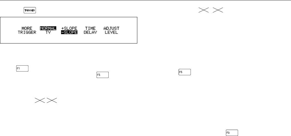
Press to open the Trigger menu.
Figure 5-11. Trigger Menu
Selecting a Trigger Source
Press to enter the MORE TRIGGER window, then
highlight TRIGGER SOURCE and press to open the
list box. Select one of the following trigger sources:
INPUT A, INPUT B, EXTERN 2V (via external trigger
input), EXTERN 0.2V (via external trigger input), or
GENERATOR (via internal waveform generator).
NOTE
You can also find the trigger source selection under the
appropriate INPUT A or INPUT B More window.
•
EXTERN 2V or EXTERN 0.2V are available as trigger
source selections. You can connect an external trigger
at the red 4-mm banana jack. Make your selection for
the appropriate TTL-compatible (Transistor-to-
Transistor Logic) trigger level (0.2V or 2V).
92B 96B
•
GENERATOR
. See Chapter 6 for more
information.
NOTE
EXTERN and GENERATOR are mutually exclusive;
selecting one deactivates the other.
Defining the Trace Start
In the MORE TRIGGER menu, highlight TRACE START
and press to open the list box.
When
Wait for trigger
is selected, the test tool needs a
trigger to display a waveform.
When
free run
is selected, and if no trigger is detected for
100 ms, the test tool provides its own trigger and the trace
still appears on the display. Use this mode for a continuous
display of a waveform.
Selecting a Trigger Slope
From the Trigger menu, press to select triggering on
either the +SLOPE or -SLOPE of the chosen input.
92B
96B


