


Chapter 5 - MODBUS-RTU Communication
75
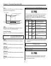
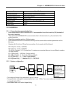
Items Specifications
Control procedure Asynchronous communication system
Communication system Half duplex system
Character system ASCII (8 bit)
Stop bit length Modbus-RTU: 1 bit, CMC BUS: 2 bit
Sum check 2 byte
Parity check None
5.3 Installation
5.3.1 Connecting the communication line
- First connect the 485 GND of MODBUS-RTU communication line to the inverter’s (CM) terminals of
the control terminals.
- Then connect the MODBUS-RTU communication line to the inverter’s (S+), (S-) terminals of the
control terminals.
- Check the connection and turn ON the inverter.
- If the communication line is connected correctly set the communication related parameters as the
following:
- Operate with DriveView if DriveView is operating, if not operate with the Keypad.
DRV-03 [Drive mode] : 3(RS485)
DRV-04 [Freq. mode] : 5(RS485)
I/O-46 [Inv. Number] :1~31 (If more than 1 inverters are connected, be sure to use different numbers
for each inverter)
I/O-47 [Baud-rate] : 9,600 bps (Factory default)
I/O-48 [Lost Mode] : 0 - No action (Factory default)
I/O-49 [Time-Out] : 10 – 1.0sec (Factory default)
I/O-50 [Comm.Prot] : 7 - Modbus-RTU, 0 – CMC BUS
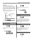
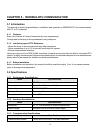
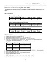
5.3.2 System configuration
- The number of drives to be connected is up to 31 drives.
- The specification of length of communication line is max. 1200m. To ensure stable communication, limit
the length below 700m.
- Use shielded wire for all control signal wiring.
Thinkpad
RS232/485
Converter
INV.#1
Comm.
Terminal
INV.#2
Comm.
Terminal
INV.#n
Comm.
Terminal
JP1 switch on the
right upper side of
control terminal
block should be
shorted using jumpe
r
to connect a
terminating resistor
at the end inverter
connected.