


Chapter 4 - Parameter Description [I/O]
65
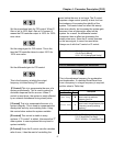
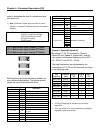
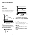
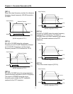
[Multi-Step Frequency Operation]
☞
Note: The frequency for ‘Speed 0’ is determined by DRV-04.
[XCEL-L, XCEL-M, XCEL-H]
By setting P1, P2 and P3 terminals to ‘XCEL-L’,
‘XCEL-M’ and ‘XCEL-H’ respectively, up to 8
different Accel and Decel times can be used. The
Accel/Decel time is set in DRV-01 ~ DRV-02 and
I/O-25 ~ I/O-38.
The Accel/Decel time is determined by the
combination of P1, P2 and P3 terminals as shown
in the following table.
Accel/Decel
Time
Parameter
Code
XCEL-H
(P3)
XCEL-M
(P2)
XCEL-L
(P1)
Accel Time-0 DRV-01
Decel Time-0 DRV-02
0 0 0
Accel Time-1 I/O-25
Decel Time-1 I/O-26
0 0 1
Accel Time-2 I/O-27
Decel Time-2 I/O-28
0 1 0
Accel/Decel
Time
Parameter
Code
XCEL-H
(P3)
XCEL-M
(P2)
XCEL-L
(P1)
Accel Time-3 I/O-29
Decel Time-3 I/O-30
0 1 1
Accel Time-4 I/O-31
Decel Time-4 I/O-32
1 0 0
Accel Time-5 I/O-34
Decel Time-5 I/O-35
1 0 1
Accel Time-6 I/O-36
Decel Time-6 I/O-37
1 1 0
Accel Time-7 I/O-38
Decel Time-7 I/O-39
1 1 1
0: OFF, 1: ON
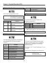
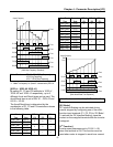
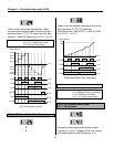
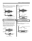
[Multi-Accel/Decel Time Operation]
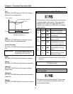
[DC-Brake]
DC Injection Braking can be activated during
inverter stopped by configuring one of the multi-
function input terminals (P1, P2, P3) to ‘DC-Bake’.
To activate the DC Injection Braking, close the
contact on the assigned terminal while the inverter
is stopped.
[2
nd
Function]
Inverter uses parameters set in FU2-81 ~ 89
when this terminal is ON. This function must be
used when motor is stopped to avoid over current
P1-CM
ON ON
Output Frequency
Time
Time
P2-CM
ON ON
Time
P3-CM
ON
Time
JOG-CM
ON
Time
FX-CM
ON
Time
RX-CM
ON
Time
ON ON
Step
0
Step
1
Step
2
Step
3
Step
4
Step
5
Step
6
Step
7
Jog
Related Functions: DRV-05 ~ DRV-07 [Step Frequency]
I/O-20 [Jog Frequency]
I/O-21 ~ I/O-24 [Step Frequency]
P1-CM
ON
Output Frequency
Time
Time
P2-CM
ON
Time
P3-CM
ON
Time
FX-CM
ON
Time
ON ON ON
ON
Ref.
Fre
q
.
Time 0 Time 1 Time 2 Time 3 Time 4 Time 5 Time 6 Time 7
Related Functions: I/O-25 ~ I/O-38 [1
st
~7
th
Accel/Decel Time]