


Chapter 4 - Parameter Description [DRV]
35
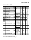
DRV-03: Drive Mode (Run/stop Method)
Select the source of Run/Stop command.
Setting Range
Select Display
Description
Keypad 0
Run/stop is controlled by Keypad.
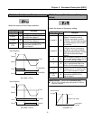
Fx/Rx-1
1
Control Terminals FX, RX and CM
control Run/Stop. (Method 1)
Fx/Rx-2
2
Control Terminals FX, RX and CM
control Run/Stop. (Method 2)
MODBUS-
RTU
3
Run/stop is controlled by Serial
Communication (MODBUS-RTU)
Refer to Chapter 5.
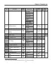
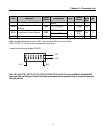
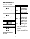
[Drive Mode: ‘Fx/Rx-1’]
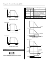
[Drive Mode: ‘Fx/Rx-2’]
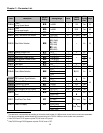
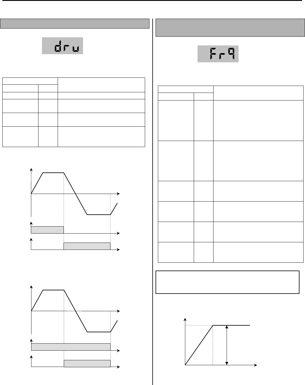
DRV-04: Frequency Mode (Frequency Setting
Method)
Select the source of frequency setting.
Setting Range
Select Display
Description
Keypad-1 0
Frequency is set at DRV-00. The
frequency is changed by pressing
[FUNC] key and entered by pressing
[FUNC] key. The inverter does not output
the changed frequency until the [FUNC]
key is pressed.
Keypad-2 1
Frequency is set at DRV-00. Press
[FUNC] key and then by pressing the
[▲], [▼] key, the inverter immediately
outputs the changed frequency. Pressing
the [FUNC] key saves the changed
frequency.
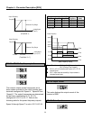
V1
2
Input the frequency reference (0-10V) to
the “V1” control terminal. Refer to the I/O-
01 to I/O-05 for scaling the signal.
I
3
Input the frequency reference (4~20mA)
to the “I” control terminal. Refer to the
I/O-06 to I/O-10 for scaling the signal.
V1+I
4
Input the frequency reference (0~10V,
4~20mA) to the “V1”,“I” control terminals.
The ‘V1’ signal overrides the ‘I’ signal.
MODBUS-
RTU
5
Frequency is set by Serial
Communication (MODBUS-RTU)
Refer to Chapter 5.
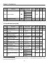
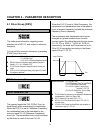
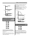
[Freq Mode: ‘V1’]
Output Frequency
FX-CM
Time
ON
RX-CM
ON
Forward
Reverse
Forward Run
Reverse Run
Output Frequency
FX-CM
Time
ON
RX-CM
ON
Forward
Reverse
Run/Stop
Direction
Output Frequency
A
nalog Signal
Input (V1)
Freq. Max
0V
10V
Reference Freq. Range
Related Functions: I/O-01 to I/O-10 [Reference Inputs]
I/O-01 to I/O-10: Scaling analog input signals (V1 and I) for
frequency reference.