


Chapter 4 - Parameter Description [DRV]
36
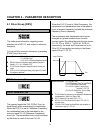
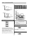
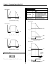
[Freq Mode: ‘I’]
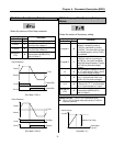
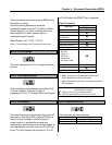
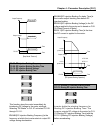
[Freq Mode: V1+’I’]
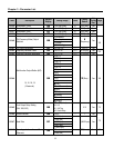
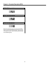
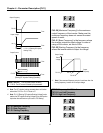
DRV-05 ~ DRV-07: Step Frequency 1 ~ 3
The inverter outputs preset frequencies set in
these codes according to the multi-function input
terminals configured as ‘Speed-L’, ‘Speed-M’ and
‘Speed-H’. The output frequencies are determined
by the binary combination of P1, P2, P3
configured in I/O-12 to I/O-17. Refer to the
following table for the preset frequency outputs.
Speed 4 through Speed 7 is set in I/O-21~I/O-24.
Binary Combination of P1, P2, P3
Speed-L Speed-M Speed-H
Output
Frequency
Step
Speed
0 0 0 DRV-00 Speed 0
1 0 0 DRV-05 Speed 1
0 1 0 DRV-06 Speed 2
1 1 0 DRV-07 Speed 3
0: ON, 1: OFF
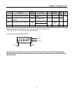
[Step Frequency Output]
DRV-08: Output Current
This code displays the output current of the
inverter in RMS.
DRV-09: Motor Speed
Output Frequency
Freq. Max
4mA
20mA
Reference Freq. Range
A
nalog Signal
Input (I)
Output Frequency
Freq. Max
0V+4m
A
Reference Freq. Range
10V+20m
A
A
nalog Signal
Input (‘V1+I’)
P1-CM
ON
Output Frequency
Time
Time
P2-CM
ON
Time
P3-CM
Time
ON
Speed 3
Speed 0
Speed 2
Speed 1
Related Functions: I/O-12 to I/O-14 [Reference Inputs]
I/O-17 [Filtering Time Constant]
I/O-12 to I/O-14: Set the terminal function of P1, P2, P3
terminal inputs.
I/O-17: Adjust response sensibility of input terminal to
eliminate contact noise.