


Chapter 4 - Parameter Description [I/O]
66
or over voltage trip.
[V1-Ext]
Inverter changes its frequency reference source
from keypad to ‘V1’ (analog voltage input) when
this terminal is ON.
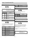
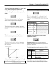
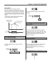
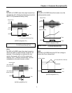
[Up, Down]
By using the Up and Down function, the drive can
accelerate to a steady speed and decelerate
down to a desired speed by using only two input
terminals.
[Up/Down Operation]
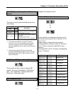
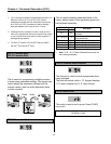
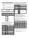
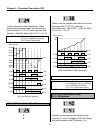
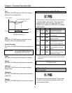
[3-Wire]
This function is for 3-wire start/stop control.
This function is mainly used with a momentary
push button to hold the current frequency output
during acceleration or deceleration.
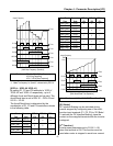
[Wiring for 3-Wire Operation, P2 set to ‘3-Wire’]
[3-Wire Operation]
[Ext Trip-A]
This is a normally open contact input. When a
terminal set to ‘Ext Trip-A’ is ON, inverter displays
the fault and cuts off its output. This can be used
as an external latch trip.
[Ext Trip-B]
This is a normally closed contact input. When a
terminal set to ‘Ext Trip-B’ is OFF, inverter
displays the fault and cuts off its output. This can
be used as an external latch trip.
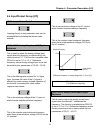
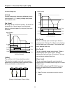
[Open-Loop]
This is used to exchange the control mode of
inverter from PID mode (Close Loop) to V/F mode
(Open Loop).
DRV-03 [Drive Mode] and DRV-04 [Frequency
Mode] are applied when the mode has been
changed.
☞
Note: This function can be used only when the inverter is
stopped.
P1-CM
‘Up’
ON
Output Frequency
Time
Time
P2-CM
‘Down’
ON
Time
FX-CM
ON
Time
Freq.
Max.
FX RX P2 CM
P2-CM
ON
Output Frequency
Time
Time
FX-CM
ON
Time
RX-CM
ON
Time
Freq.
Max.
Freq.
max.