


Chapter 4 - Parameter Description [I/O]
64
waits to determine the loss of a reference signal
until times out.
☞
Note: I/O-48 and I/O-49 also apply when DRV-04 is set to
‘Keypad-1’ or ‘Keypad-2’ for determining the loss of command
frequency.
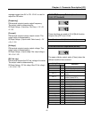
I/O-12: Multi-function Input Terminal ‘P1’ Define
I/O-13: Multi-function Input Terminal ‘P2’ Define
I/O-14: Multi-function Input Terminal ‘P3’ Define
Multi-function input terminals can be defined for
many different applications. The following table
shows the various definitions for them.
Setting Range
Select Display
Description
Speed-L
0
Multi-step speed - Low
Speed-M
1
Multi-step speed - Mid
Speed-H
2
Multi-step speed - High
XCEL-L
3
Multi-accel/decel - Low
XCEL-M
4
Multi-accel/decel - Mid
XCEL-H
5
Multi-accel/decel - High
DC-Brake
6
DC injection braking during stop
2nd
Func
7
Reserved for future use
-Reserved-
8
Exchange to commercial power line
V1-Ext
9
Exchange freq. reference source to
V1 input
Up
10
Up drive
Down
11
Down drive
3-Wire
12
3 wire operation
Ext Trip-A
13
External trip A
Setting Range
Select Display
Description
Ext Trip-B
14
External trip B
-Reserved-
15
Reserved for future use
Open-Loop
16
Exchange between PID mode and
V/F mode
-Reserved-
17
Reserved for future use
Analog Hold
18
Hold the analog input signal
XCEL Stop
19
Disable accel and decel
20
21
22
23
24
25
-Reserved-
26
Reserved for future use
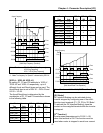
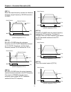
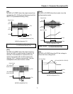
[Speed-L, Speed-M, Speed-H]
By setting P1, P2, P3 terminals to ‘Speed-L’,
‘Speed-M’ and ‘Speed-H’ respectively, inverter
can operate at the preset frequency set in DRV-
05 ~ DRV-07 and I/O-20 ~ I/O-24.
The step frequencies are determined by the
combination of P1, P2 and P3 terminals as shown
in the following table.
Step
Frequency
Parameter
Code
Speed-H
(P3)
Speed-M
(P2)
Speed-L
(P1)
Step Freq-0 DRV-00 0 0 0
Step Freq-1 DRV-05 0 0 1
Step Freq-2 DRV-06 0 1 0
Step Freq-3 DRV-07 0 1 1
Step Freq-4 I/O-21 1 0 0
Step Freq-5 I/O-22 1 0 1
Step Freq-6 I/O-23 1 1 0
Step Freq-7 I/O-24 1 1 1
0: OFF, 1: ON
☞ I/O-20 [Jog Frequency] can be used as one of the step
frequencies.
☞ If the ‘Jog’ terminal is ON, inverter operates to Jog frequency
regardless of other terminal inputs.
Related Functions: DRV-04 [Frequency Mode]
I/O-02 [V1 Input Minimum Voltage]
I/O-07 [I Input Minimum Current]
I/O-48 [Lost command]
I/O-49
[
Time out
]