


Chapter 1 - Installation
14
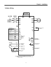
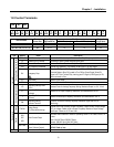
1.8.1 Wiring Control Terminals
Precautions on Wiring
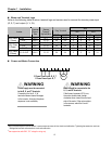
Use shielded wires or twisted wires for control circuit wiring, and separate these wires from the main
power circuits and other high voltage circuits.
Control Circuit Terminal
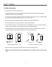
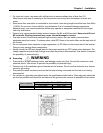
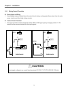
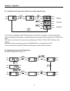
The input terminals can be selected for either NPN or PNP type logic by changing switch J1. CM
terminal is the common terminal for the input signals.
Do not apply voltage to any control input terminals (FX, RX, P1, P2, P3, JOG, BX, CM, etc).
24 V
FX
CM
Resistor
CM
J1
NPN
SW J1
Inside Inverter
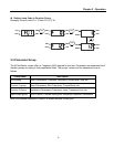
24 V
FX
CM
Resistor
CM
J1
DC24V
PNP
SW J1
Inside Inverter
CAUTION