


Chapter 4 - Parameter Description [I/O]
63
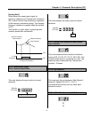
This is the filtering time constant for ‘I’ signal input.
If the ‘I’ signal is affected by noise causing
unstable operation of the inverter, increase this
value. Increasing this value makes response time
slower.
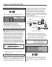
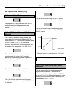
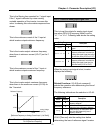
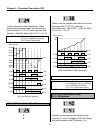
This is the minimum current of the ‘I’ input at
which inverter outputs minimum frequency.
This is the inverter output minimum frequency
when there is minimum current (I/O-07) on the ‘I’
terminal.
This is the maximum current of the ‘I’ input at
which inverter outputs maximum frequency.
This is the inverter output maximum frequency
when there is the maximum current (I/O-09) on
the ‘I’ terminal.
[Reference Frequency vs. Analog Current Input, I (4 to 20mA)]
I/O-11: Criteria for Analog Input Signal Loss
This is to set the criteria for analog input signal
loss when DRV-04 [Frequency Mode] is set to
‘V1’, ‘I’ or ‘V1+I’. Following table shows the setting
value.
Setting Range
Select Display
Description
None
0
Does not check the analog input
signal.
half of x1
1
The inverter determines that the
frequency reference is lost when the
analog input signal is less than half of
the minimum value (I/O-02 or I/O-07).
below x1
2
The inverter determines that the
frequency reference is lost when the
analog input signal is less than the
minimum value (I/O-02 or I/O-07).
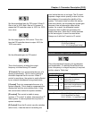
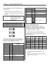
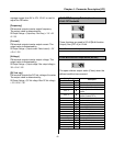
When the analog input signal is lost, inverter
displays the following.
Related Functions: I/O-48 [Lost command]
selects the operation after determining the loss of
frequency reference.
The following table shows the selection in I/O-48.
Setting Range
Select Display
Description
None
0
Continuous operating after loss of
frequency reference.
FreeRun
1
Inverter cuts off its output after
determining loss of frequency reference.
Stop
2
Inverter stops by its Decel pattern and
Decel time after determining loss of
frequency reference.
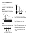
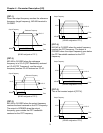
I/O-49 [Time out] sets the waiting time before
determining the loss of reference signal. Inverter
Reference Frequency
I/O-10
A
nalog Voltage
Input (V1)
I/O-08
I/O-07 I/O-09
Related Functions: DRV-04 [Frequency Mode]
FU1-20 [Maximum Frequency]