


Chapter 1 - Installation
9
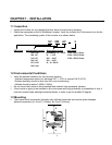
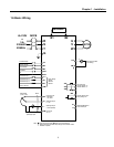
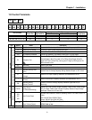
1.6 Basic Wiring
2
30/460V
50/60Hz
U
V
W
G
R
S
T
or
3
Φ,
MCCB
FX
RX
BX
RST
P1
P3
CM
VR
V1
I
CM
+
FM
CM
30A
30B
30C
MO
MG
Output Frequency Meter
(0~10V Analog)
P2
MOTOR
Potentiometer
(1 kohm, 1/2W)
Speed signal Input
1
Forward Run/Stop
Reverse Run/Stop
Inverter Disable
Fault Reset
Multi-function Input 1
Multi-function Input 2
Multi-function Input 3
Common Terminal
Factory Setting:
‘Speed-L’
‘Speed-M’
‘Speed-H’
Power supply for
speed signal:
+ 12V, 10mA
Speed signal input:
0 ~ 10V
Speed signal input:
4 ~20mA (250ohm)
Common for
VR, V1, I
Fault output relay
Less than AC250V, 1A
Less than DC30V, 1A
Less than DC24V, 50mA
Factory setting: ‘Run’
Note) display main circuit terminals, display control circuit terminals.
1. Analog speed command can be set by Voltage, Current and both of them.
2. DB resistor is optional.
B2B1
FM
JOG
Jog
Shield
DB Resistor
2
RS485 & MODBUS-RTU
Communication port
S+
S-
1Φ,
230V