


Chapter 4 - Parameter Description [I/O]
62
4.4 Input/Output Group [I/O]
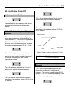
I/O-00: Jump to Desired Code #
Jumping directly to any parameter code can be
accomplished by entering the desired code
number.
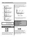
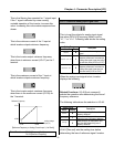
I/O-01 ~ I/O-05: Analog Voltage Input (V1) Signal
Adjustment
This is used to adjust the analog voltage input
signal when the frequency is referenced by the
control terminal ‘V1’. This function is applied when
DRV-04 is set to ‘V1’ or ‘V1+I’. Reference
frequency versus Analog voltage input curve can
be made by four parameters of I/O-02 ~ I/O-04.
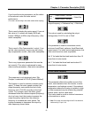
This is the filtering time constant for V1 signal
input. Increase this value if the V1 signal is
affected by noise causing unstable operation of
the inverter. Increasing this value makes
response time slower.
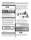
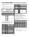
This is the minimum voltage of the V1 input at
which inverter outputs minimum frequency.
This is the inverter output minimum frequency
when there is the minimum voltage (I/O-02) on the
V1 terminal.
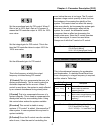
This is the maximum voltage of the V1 input at
which inverter outputs maximum frequency.
This is the inverter output maximum frequency
when there is the maximum voltage (I/O-03) on
the V1 terminal.
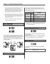
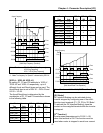
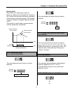
[Reference Frequency vs. Analog Voltage Input, V1 (0 to 10V)]
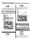
I/O-06 ~ I/O-10: Analog Current Input (I) Signal
Adjustment
This is used to adjust the analog current input
signal when the terminal ‘I’ references the
frequency. This function is applied when DRV-04
is set to ‘V1’ or V1+I’. Reference frequency versus
Analog current input curve can be made by four
parameters of I/O-07 ~ I/O-10.
Reference Frequency
I/O-05
A
nalog Voltage
Input (V1)
I/O-03
I/O-02 I/O-04
Related Functions: DRV-04 [Frequency Mode]
FU1-20 [Maximum Frequency]