


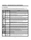


Chapter 6 - Troubleshooting & Maintenance
97
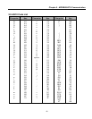
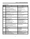
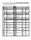
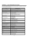
6.7 Daily and Periodic Inspection Items
Period
Inspection
Location
Inspection
Item
Inspection
Daily
1 year
2 year
Inspection Method Criterion
Measuring
Instrument
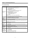
Ambient
Environ-
ment
Is there any dust?
Is the ambient temperature and
humidity adequate?
Ο
Refer to the precautions Temperature:
-10~+40 no
freezing.
Humidity: Under
90% no dew
Thermometer,
Hygrometer,
Recorder
Equipment
Is there any abnormal oscillation
or noise
Ο
Use sight and hearing No abnormality
All
Input
Voltage
Is the input voltage of the main
circuit normal
Ο
Measure the voltage between
the terminals R, S, T
Digital Multi-
Meter/Tester
All
Megger check (between the main
circuit and the ground)
Are any fixed parts removed?
Are there any traces of
overheating at each component’s
cleaning?
Ο
Ο
Ο
Ο
Undo the inverter connections
short the terminals R, S, T, U,
V, W and measure between
these parts and the ground.
Tighten the screws.
Visual check.
Over 5MΩ
No fault
DC 500V
class Megger
Conductor/
Wire
Is the conductor rusty?
Is the wire coating damaged?
Ο
Ο
Visual check No fault
Terminal
Is there any damage?
Ο
Visual check No fault
IGBT
Module
/Diode
Module
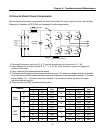
Check the resistance between
each of the terminals.
Ο
Undo the inverter connection
and measure the resistance
between R, S, T ⇔ P, N and
U, V, W ⇔ P, N with a tester.
(Refer ‘How to
Check Power
Components”)
Digital Multi-
Meter/Analog
Tester
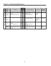
Smoothing
Capacitor
Is there any liquid coming out?
Is the safety pin out, and is there
any swelling?
Measure the capacitance.
Ο
Ο
Ο
Visual check.
Measure with a capacitance-
measuring device.
No fault
Over 85% of the
rated capacity
Capacitance
Measuring
Device
Relay
Is there any chattering noise
during operation?
Is there any damage to the
contact
Ο
Ο
Auditory check.
Visual check.
No fault
Main Circuit
Resistor
Is there any damage to the
resistor insulation?
Is the wiring in the resistor
damaged (open)?
Ο
Ο
Visual check.
Disconnect one of the
connections and measure
with a tester.
No fault
Error must be
within ±10%
the displayed
resistance
Digital Multi-
Meter/Analog
Tester
Control Circuit
Protective Circuit
Operation
Check
Is there any unbalance between
each phases of the output
voltage?
Nothing must be wrong with
display circuit after executing the
sequence protective operation
Ο
Ο
Measure the voltage between
the output terminals U, V and
W.
Short and open the inverter
protective circuit output.
The voltage
balance between
the phases for
200V (800V)
class is under
4V (8V).
The fault circuit
operates
according to the
sequence.
Digital Multi-
Meter/Rectifyi
ng Voltmeter