


Chapter 1 - Installation
10
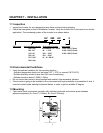
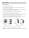
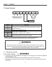
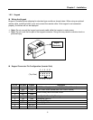
1.7 Power Terminals
R S T B1 B2 U V W
Symbols Functions
R
S
T
AC Line Input Terminals
3(1) phase, 200 ~ 230V AC for 200V Class Units and 380 ~ 460V AC
for 400V Class Units.
1 Phase Input Terminals: R and T
U
V
W
3 Phase Output Terminals to Motor
(3 Phase, 200 ~ 230VAC or 380 ~ 460VAC)
B1
B2
Dynamic Braking Resistor Connection Terminals
“Suitable for use on a circuit capable of delivering not more than 10,000 rms symmetrical amperes,
240 volts maximum for 230V class models and 480 volts maximum for 460V class models.”
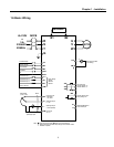
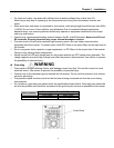
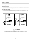
1.7.1 Wiring Power Terminals
Precautions on Wiring
The internal circuits of the inverter will be damaged if the incoming power is connected and applied to
output terminals (U, V, W).
Use ring terminals with insulated caps when wiring the input power and motor wiring.
Do not leave wire fragments inside the inverter. Wire fragments can cause faults, breakdowns, and
malfunctions.
Normal stray capacitance between the inverter chassis and the power devices inside the
inverter and AC line can provide a high impedance shock hazard. Do not apply power to the
inverter if the inverter frame (Power terminal G) is not grounded.
Moto
r
DB Resistor
3 Phase Power Input: R, S, T
1 Phase Power Input: R, T
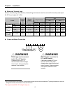
WARNING
WARNING