


Chapter 4 - Parameter Description [I/O]
68
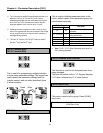
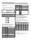
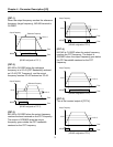
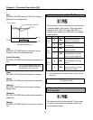
These codes set the step frequencies. These
frequencies are applied when the multi-function
input terminals (P1, P2, P3) select the step. See
[Speed-L, Speed-M, Speed-H] in I/O-12 ~ I/O-14.
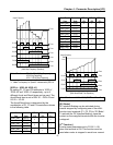
[‘JOG’ and ‘Multi-Step’ Operation]
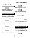
I/O-25 ~ I/O-38: 1
st
~ 7
th
Accel/Decel Time
▼
▼
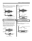
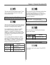
These codes are applied when the multi-function
input terminals (P1, P2, P3) select the
Accel/Decel time. See [XCEL-L, XCEL-M, XCEL-
H] in I/O-12 ~ I/O-14.
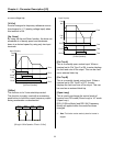
[Multi-Accel/Decel Time Operation]
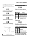
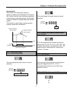
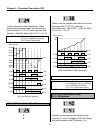
I/O-40: FM (Frequency Meter) Output
I/O-41: FM Adjustment
Frequency meter displays the inverter output
Frequency, Current, Voltage and DC link voltage
with pulse signals on the FM terminal. The
Related Functions: DRV-05 ~ DRV-07 [Step Frequency 1 ~ 3]
I/O-12 ~ I/O-14 [Multi-function inputs]
I/O-17 [Filtering Time Constant]
Related Functions: DRV-01 ~ DRV-02 [Accel/Decel Time]
FU2-70 [Reference Freq. for Accel/Decel]
FU2-71 [Accel/Decel Time Scale]
I/O-12 ~ I/O-14 [Multi-function inputs]
P1-CM
ON
Output Frequency
Time
Time
P2-CM
Time
P3-CM
Time
Speed 1
JOG-CM
Time
FX-CM
Time
RX-CM
Time
ON ON ON
ON ON
ON
ON
ON
ON
Speed 0
Speed 2
Speed 3
Speed 4
Speed 5
Speed 6
Speed 7
JOG
P1-CM
ON
Output Frequency
Time
Time
P2-CM
ON
Time
P3-CM
ON
Time
FX-CM
ON
Time
ON ON ON
ON
Ref.
Fre
q
.
Time 0 Time 1 Time 2 Time 3 Time 4 Time 5 Time 6 Time 7
Related Functions: I/O-25 ~ I/O-38 [1
st
~7
th
Accel/Decel Time]