


Chapter 6 - Troubleshooting & Maintenance
95
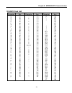
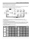
6.5 How to Check Power Components
Before checking the power components, be sure to disconnect AC Input supply and wait until the Main
Electrolytic Capacitors (DCP-DCN) are discharged to safe voltage levels.
1) Disconnect the power input line (R, S, T) and the inverter output to the motor (U, V, W).
2) Verify whether the inverter terminal R, S, T, U, V, W, B1, B2 is shorted or open by changing the
polarity of the tester.
3) Verify capacitor has discharged before testing.
4) The tester should display several mega-ohms when open. The tester can display terminal is shorted
for a short time and then display several mega-ohms because of the electrolytic capacitor. The tester
should display 1 Ω ~ 10 Ω when terminal is shorted. If all measured values are about the same,
individual modules are OK.
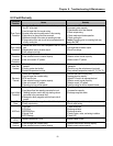
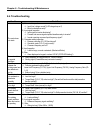
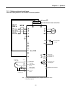
4) Diode module and IGBT module checking points:
Test Polarity Test Polarity
Elements
+ -
Measured
Value
Element
+ -
Measured
Value
R B1 Short R DCN Open
D1
B1 R Open
D4
DCN R Short
S B1 Short S DCN Open
D2
B1 S Open
D5
DCN S Short
T B1 Short T DCN Open
Diode
Module
D3
B1 T Open
D6
DCN T Short
U B1 Short U DCN Open
Tr1
B1 U Open
Tr4
DCN U Short
V B1 Short V DCN Open
Tr3
B1 V Open
Tr6
DCN V Short
W B1 Short W DCN Open
IGBT
Module
Tr5
B1 W Open
Tr2
DCN W Short
R
G
E
G
E
G
E
G
E
G
E
G
E
S
T
U
V
W
G
E
DCP
B1
DCN
Char
g
e resisto
r
Contactor
+
Electrolytic
capacitors
B2
Current Sensing Resistor
D1 D2 D3
D4 D5 D6
TR1 TR3 TR5
TR4 TR6 TR2