


108
EMC INSTALLATION GUIDE
CMC inverters are tested to meet Electromagnetic Compatibility (EMC) Directive 89/336/EEC and Low
Voltage (LV) Directive 73/23/EEC using a technical construction file. However, Conformity of the inverter
with CE EMC requirements does not guarantee an entire machine installation complies with CE EMC
requirements. Many factors can influence total machine installation compliance.
Essential Requirements for CE Compliance
Following conditions must be satisfied for CMC inverters to meet the CE EMC requirements.
1. CE compatible CMC inverter
2. Installing inverter in an EMC enclosure
3. Grounding enclosure and shielded parts of wire
4. RFI filter on inverter input side
5. Using shielded cable
6. Ferrite core on inverter output side
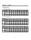
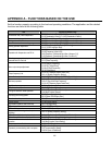
RFI FILTERS
THE L.G. RANGE OF POWER LINE FILTERS FF (Footprint) – FE (Standard) SERIES, HAVE BEEN SPECIFICALLY
DESIGNED WITH HIGH FREQUENCY CMC INVERTERS, THE USE L.G. FILTERS, WITH THE INSTALLATION ADVICE
OVERLEAF HELP TO ENSURE TROUBLE FREE USE ALONG SIDE SENSITIVE DEVICES AND COMPLIANCE TO
CONDUCTED EMISSION AND IMMUNITY STANDARDS TO EN50081
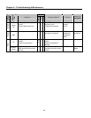
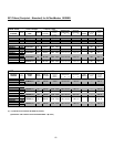
CAUTION
IN CASE OF A LEAKAGE CURRENT PROTECTIVE DEVICES IS USED ON POWER SUPPLY, IT MAY BE FAULT AT
POWER-ON OR OFF.
IN AVOID THIS CASE, THE SENSE CURRENT OF PROTECTIVE DEVICE SHOULD BE LARGER THAN VALUE OF LAKAGE
CURRENT AT WORST CASE IN THE BELOW TABLE.
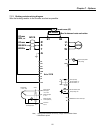
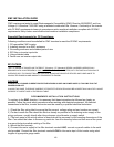
RECOMMENDED INSTALLATION INSTRUCTIONS
To conform to the EMC directive, it is necessary that these instructions be followed as closely as
possible. Follow the usual safety procedures when working with electrical equipment. All electrical
connections to the filter, inverter and motor must be made by a qualified electrical technician.
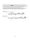
1-) Check the filter rating label to ensure that the current, voltage rating and part number are correct.
2-) For best results the filter should be fitted as closely as possible to the incoming mains supply of the
wiring enclosure, usually directly after the enclosures circuit breaker or supply switch.
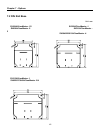
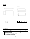
3-) The back panel of the wiring cabinet of board should be prepared for the mounting dimensions of the
filter. Care should be taken to remove any paint etc. from the mounting holes and face area of the panel
to ensure the best possible earthing of the filter.
4-) Mount the filter securely.
5-) Connect the mains supply to the filter terminals marked LINE, connect any earth cables to the earth
stud provided. Connect the filter terminals marked LOAD to the mains input of the inverter using short
lengths of appropriate gauge cable.